
Printing press with bearer rings

A technology for printing presses and rolling pillows, applied in printing presses, rotary presses, printing, etc., can solve problems such as inability to suppress torsional vibrations, and achieve the effect of avoiding interfering relative motion

Inactive Publication Date: 2011-07-27
HEIDELBERGER DRUCKMASCHINEN AG
View PDF3 Cites 2 Cited by
  • Summary
  • Abstract
  • Description
  • Claims
  • Application Information

AI Technical Summary

Problems solved by technology

But because the support plates do not roll against each other, these support plates are not able to dampen torsional vibrations

Method used


Image

  • Printing press with bearer rings
  • Printing press with bearer rings
  • Printing press with bearer rings

Examples


Embodiment Construction

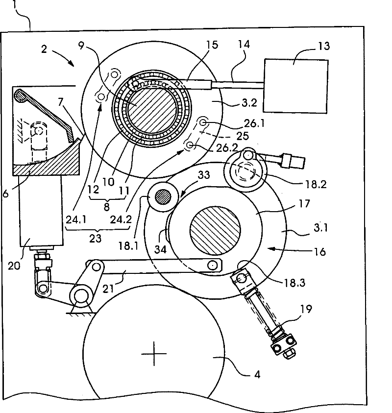
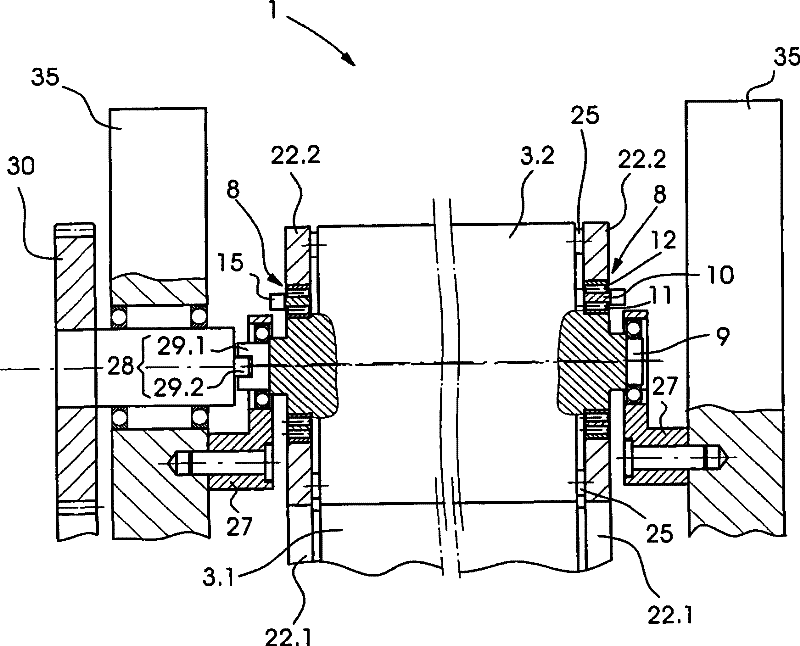
[0024] figure 1 with figure 2 A detail of a printing press 1 is shown in . This detail shows the anilox inking unit 2 of the printing press 1 . The anilox inking unit 2 comprises an inking roller 3.1 and an anilox roller 3.2, which rests against the inking roller 3.1. The inking roller 3.1 can be mounted on a printing plate cylinder 4 in a press-on manner and can be detached from the printing plate cylinder. An ink fountain 6 with a doctor blade 7 is assigned to the screen roller 3.2. There is also an impression cylinder and a blanket cylinder, but not shown in the drawing, which rest against the plate cylinder 4 and the impression cylinder during the printing operation.

[0025] On either side of the engraved roll 3.2 there is a support device 8 which is arranged on the shaft 9 of the engraved roll 3.2. The bearing devices 8 each comprise an eccentric sleeve 10 , a first pivot bearing 11 and a second pivot bearing 12 . The eccentric sleeve 10 has a bore which is not co...


PUM


Abstract

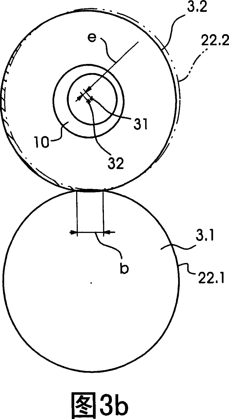
The present invention relates to a printing press (1) includes a first rotary body (3.1) with a first bearer ring (22.1) and a second rotary body (3.2) with an axle (9) which eccentrically supports a second bearer ring (22.2). The second bearer ring is in rolling contact with the first bearer ring (22.1) and is rotatably coupled to the second rotary body (3.2).

Description

technical field [0001] The invention relates to a printing machine with a pillow ring. Background technique [0002] Printing press cylinders or rollers rolling against each other generate bending or torsional vibrations. The roller channels are the cause of the bending vibrations, and when these roller channels roll past each other, the radial force drops abruptly and builds up again. This disturbing effect is known as so-called channel shock. Torsional vibrations can have different causes. One possible cause is that the reset torque builds up and reverses periodically. The restoring torque is produced by rolling action of the blanket with which one of the two rollers rolled against each other is covered. When the blanket emerges from the cylinder channel of the other cylinder, the blanket behaves viscoelastically, wherein the blanket generates a force component which generates a restoring torque. Another possible reason is an effect known by the name "pure rolling". ...

Claims


Application Information

Patent Timeline
Patent Type & Authority Patents(China)
IPC IPC(8): B41F13/21
CPCB41F13/21
Inventor D·布赫利特S·德米尔J·米歇尔斯R·米勒D·沙夫拉特J·席尔法特W·舍恩贝格尔B·施瓦布M·蒂勒曼
Owner HEIDELBERGER DRUCKMASCHINEN AG
Learn More