Trust bearing device

A thrust bearing, bearing surface technology, applied in the direction of bearings, bearing components, shafts and bearings, etc., can solve problems such as uneven wear and uneven bias

Inactive Publication Date: 2009-03-25
MAN ENERGY SOLUTIONS SA
View PDF0 Cites 1 Cited by
  • Summary
  • Abstract
  • Description
  • Claims
  • Application Information

AI Technical Summary

Problems solved by technology

Uneven biasing of the thrust bearing arrangement a leads to uneven wear not only on the bearing surface b but also on the bearing surface e

Method used


Image

  • Trust bearing device
  • Trust bearing device
  • Trust bearing device

Examples


Embodiment Construction

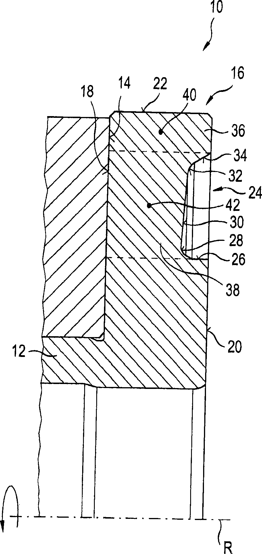
[0021] exist figure 1 Shown in is the upper half of a longitudinal section along the axis of rotation R for axially supporting a shaft 12 according to the invention. Thrust bearing arrangement 10 has a stationary bearing surface 14 arranged in the housing, which lies in a plane extending at right angles to axis R of rotation.

[0022] The shaft 12 is provided at its free end with a radially outwardly projecting thrust bearing shoulder 16 . Thrust bearing shoulder 16 has a rectangular basic shape in cross section and merges into the peripheral surface of shaft 12 with the formation of free cuts. The thrust bearing shoulder 16 has a bearing surface 18 which also extends at right angles to the axis of rotation R, by means of which the bearing shoulder 16 is pretensioned on the bearing surface 14 for axial support.

[0023] Thrust bearing shoulder 16 is provided with a groove 24 on its rear side 20 facing away from bearing surface 18 at a distance from its peripheral surface 22...


PUM


Abstract

The invention relates a thrust bearing device for high rotation speed, which comprises a support surface with fixed position (14), a thrust bearing beading (16) arranged on a shaft to be supported, and a bearing surface (18) for axially supporting at a supporting surface (14). The thrust bearing beading which is in rotational symmetry exhibits a mass distribution in radial direction with respect to the bearing surface. Bending moment is developed through the mass distribution during high rotation speed in the thrust bearing beading. The bending moment is effected in a direction of the bearing surface, and works against deformation of the bearing surface from the supporting surface, where the deformation is caused by the high rotation speed.

Description

technical field [0001] The invention relates to a thrust bearing arrangement, in particular for high rotational speeds, with a stationary support surface and a thrust bearing shoulder arranged on the shaft to be supported, which has a thrust bearing for axial support on the support surface bearing surface. Background technique [0002] Thrust bearing arrangements of the type mentioned at the outset have been known for a long time. An example of a known thrust bearing arrangement in the prior art is at Figure 4 , where the upper half of the thrust bearing arrangement a is shown in longitudinal section along the axis of rotation R. [0003] Thrust bearing arrangement a has a stationary bearing surface b which is arranged, for example, in a bearing housing of thrust bearing arrangement a. The shaft c is provided with a thrust bearing shoulder d for axial support. The thrust bearing shoulder d has a bearing surface e extending at right angles to the axis of rotation R of the...

Claims


Application Information

Patent Timeline
Patent Type & Authority Applications(China)
IPC IPC(8): F16C33/58
CPCF16C17/24F16C15/00F16C3/02F16C17/04F16C17/00F16C35/00
Inventor G·里德D·武茨
Owner MAN ENERGY SOLUTIONS SA
Why Eureka
Try Eureka