Test chart, test chart measurement method, and test chart measurement apparatus

A technology of test charts and patterns, applied to measuring devices, inking devices, printing devices, etc., can solve the problems of difficulty in ensuring the delivery of paper, increasing manufacturing costs, and difficulty in ensuring the relative position accuracy of line sensors

Inactive Publication Date: 2009-04-01
FUJIFILM CORP
View PDF3 Cites 28 Cited by
  • Summary
  • Abstract
  • Description
  • Claims
  • Application Information

AI Technical Summary

Problems solved by technology

Having this type of high-resolution reading mechanism within the printing unit adds cost
[0008] In addition, if a reading device is constituted by connecting together a plurality of line sensors described in Japanese Patent Application Laid-Open Publication No. 2006-284406, it is difficult to ensure relative positional accuracy between the line sensors, and it is difficult to ensure relative positional accuracy with respect to The paper is conveyed accurately in the conveying direction, and this is also a factor that increases manufacturing costs

Method used


Image

  • Test chart, test chart measurement method, and test chart measurement apparatus
  • Test chart, test chart measurement method, and test chart measurement apparatus
  • Test chart, test chart measurement method, and test chart measurement apparatus

Examples


Embodiment Construction

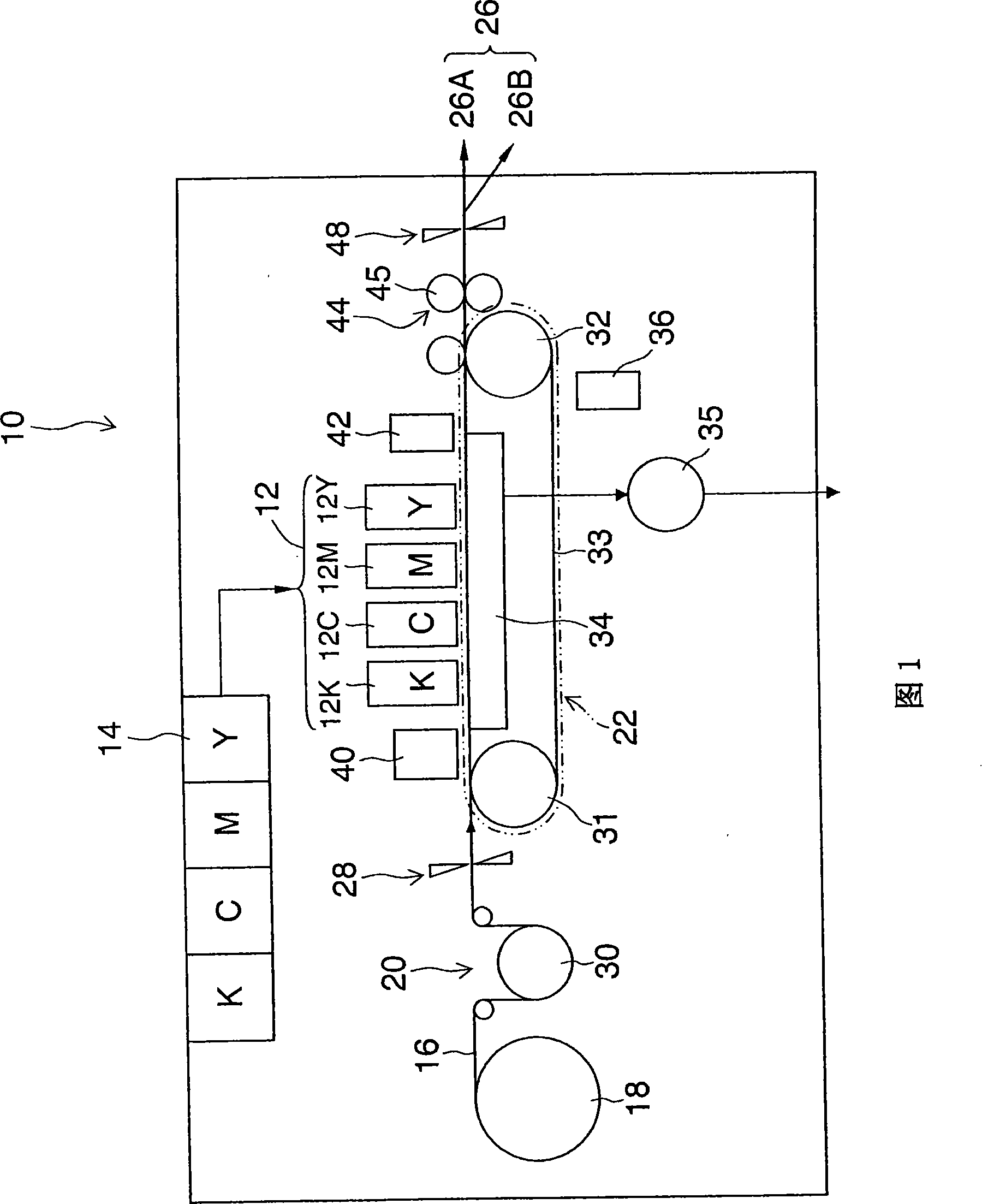
[0072] Referring to the accompanying drawings, preferred embodiments of the present invention will be described below.

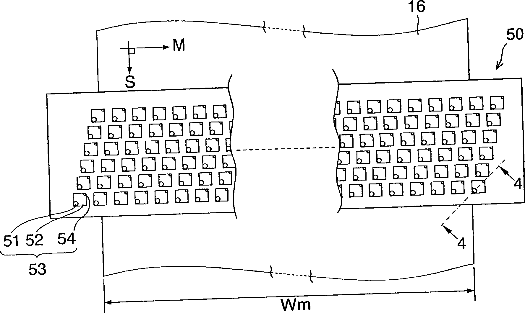
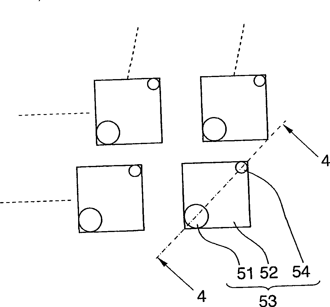
[0073] Here, an application example of measurement of dot deposition positions and dot diameters of ink dots formed by an inkjet recording apparatus is described. First, the general structure of an inkjet recording apparatus will be described.

[0074] Description of Inkjet Recording Device

[0075] FIG. 1 is an overall schematic diagram of an inkjet recording apparatus. As shown in FIG. 1 , the inkjet recording apparatus 10 includes: a printing unit 12 having a plurality of inkjet recording heads (corresponding to “liquid ejection heads”, hereinafter referred to as “print heads”) 12K, 12C , 12M and 12Y, the inkjet recording heads are respectively set for ink colors of black (K), cyan (C), magenta (M) and yellow (Y); ink storage and loading unit 14 for Stores ink to be supplied to the print heads 12K, 12C, 12M, and 12Y; paper supply unit 18 for supplyin...


PUM


Abstract

A test chart is recorded on a recording medium by means of a line head having a plurality of recording elements by causing the plurality of recording elements to perform recording operation while moving the recording medium and the line head relatively to each other in a relative movement direction. The test chart includes: a line pattern block which includes a plurality of line patterns respectively corresponding to the plurality of recording elements, the plurality of line patterns being arranged at a prescribed interval or above so as to be separated from each other, wherein the plurality of line patterns include reference line patterns arranged on both end regions of the line pattern block, the reference line patterns having line characteristic quantities different from the others of the plurality of line patterns. Also, the invention provides a test chart, measure method and measure device thereof.

Description

technical field [0001] The present invention relates to a test chart and its measuring method, a test chart measuring device and a computer program for causing a computer to measure a test chart, and more particularly to a test chart and a technique for measuring it, suitable for measuring an inkjet recording device Dot characteristics (for example, deposition position, dot diameter, and occurrence of ejection failures and other abnormalities) were recorded for each recording element in the line printhead installed in . Background technique [0002] In an inkjet recording apparatus having a recording head including a plurality of ink ejection ports (nozzles), a problem in image quality arises due to density variations (density inconsistencies) in recorded images due to variations in nozzle ejection characteristics. In the case of a series (shuttle) scanning method in which image recording is performed by moving the recording head through a prescribed printing area multiple t...

Claims


Application Information

Patent Timeline
Patent Type & Authority Applications(China)
IPC IPC(8): B41J2/01B41J2/165B41J29/393G01B11/00
CPCB41J2/2146B41J2/2142B41J2202/21B41J29/393B41J29/38
Inventor 山崎善朗
Owner FUJIFILM CORP
Why Eureka
Try Eureka