Card connector

A technology of card connectors and moving contacts, which is applied in the field of card connectors and can solve problems such as inapplicability to card installation

Inactive Publication Date: 2009-04-01
ALPS ALPINE CO LTD
View PDF0 Cites 7 Cited by
  • Summary
  • Abstract
  • Description
  • Claims
  • Application Information

AI Technical Summary

Problems solved by technology

[0004] However, the conventional card connectors as described above can only be applied to the case where the card is held on the cover, and cannot be applied to the case where the card is mounted to the mounting portion of the housing.

Method used


Image

  • Card connector
  • Card connector
  • Card connector

Examples


Embodiment Construction

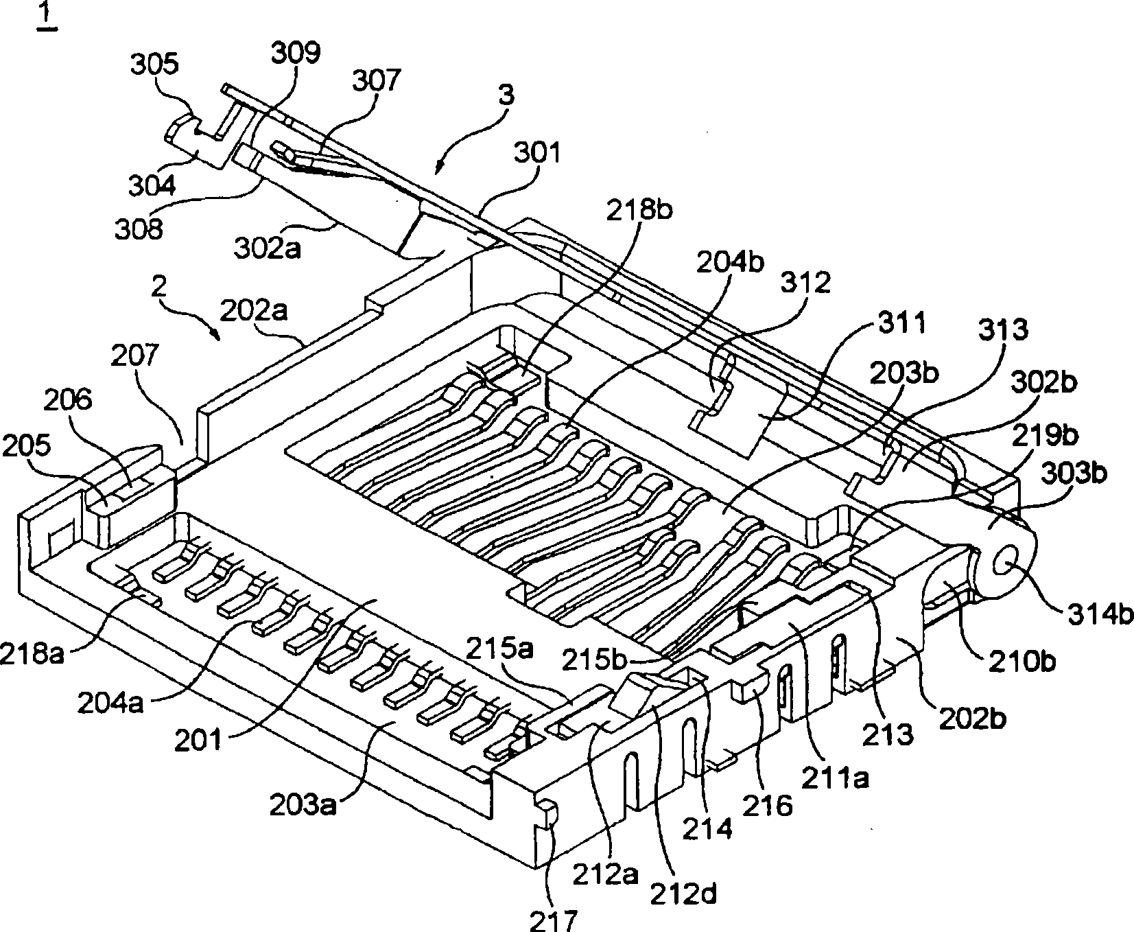
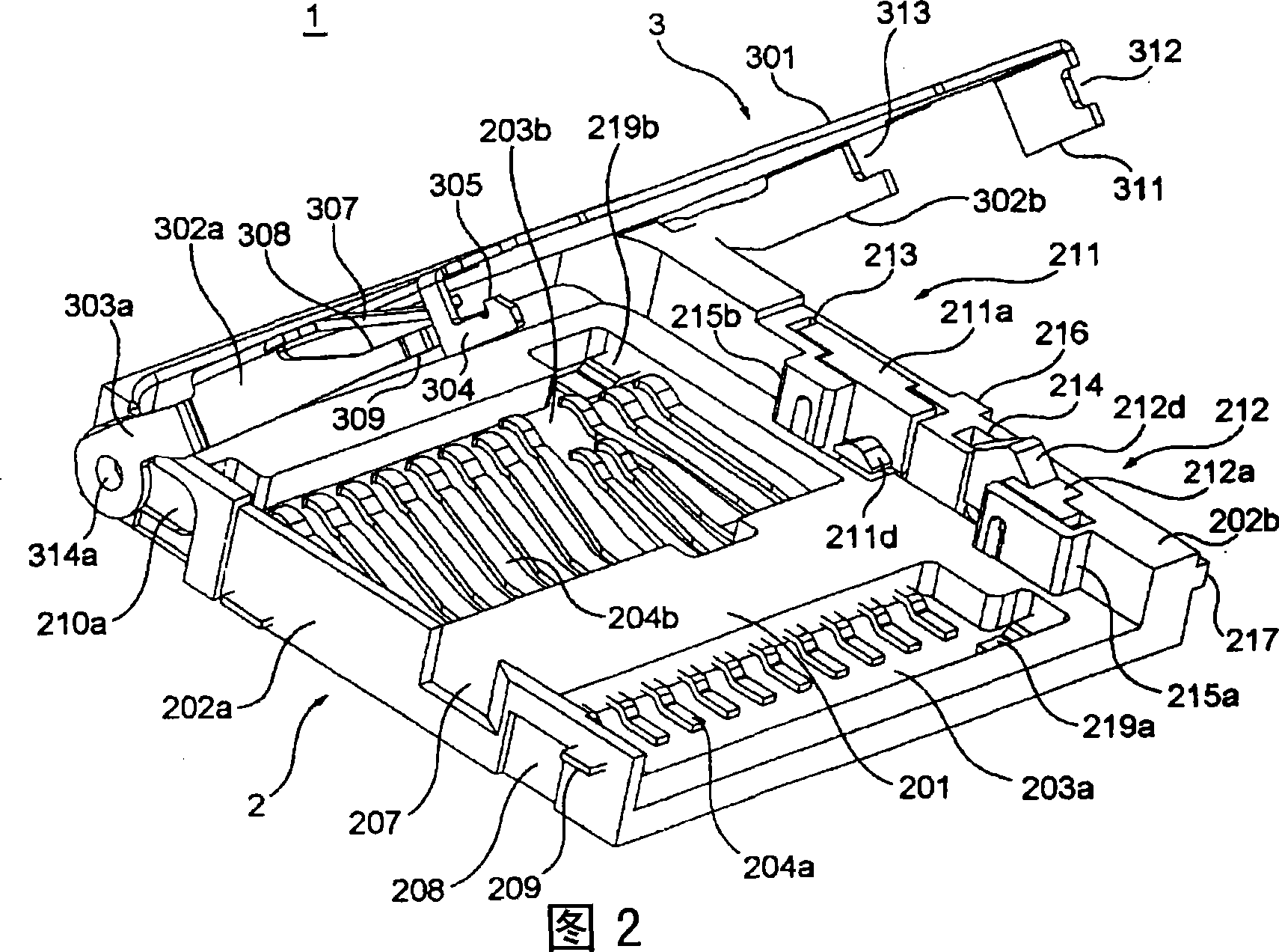
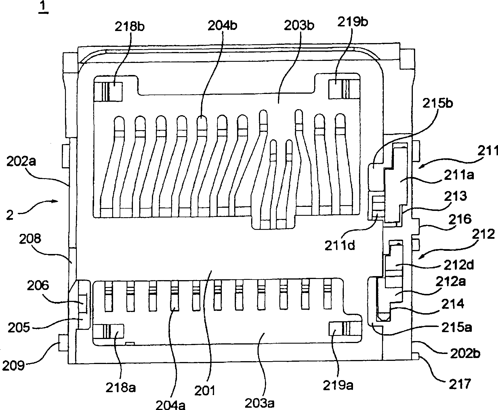
[0033] Hereinafter, an embodiment of the present invention will be described in detail with reference to the accompanying drawings. figure 1 2 is a perspective view for explaining the configuration of a card connector (hereinafter, simply referred to as a "connector") 1 according to an embodiment of the present invention. image 3 It is a top view of the connector 1 of this embodiment. and also, figure 1 And FIG. 2 illustrates the state in which the cover of the connector 1 is opened. in addition, figure 1 The connector 1 is shown from the right side, and FIG. 2 shows the connector 1 from the left side. also, image 3 The cover that the connector 1 has is omitted. Below, for convenience, the connector 1 figure 1 The left side of the paper shown in the figure is called "the front side of the connector 1" or only the "front side", and the right side of the paper shown in the same figure is called "the rear side of the connector 1" or only the "front side". Called the "rea...


PUM


Abstract

A card connector can detect a state that a card is reasonably installed and simultaneously a cover is closed even the card connector is provided with a structure that the card is installed on the installing part of casing. The card connector (1) is provided with a casing (2) and the cover (3). The casing (2) is provided with a contact (204b) connected with the card and installing parts of contact (204b) and card. The cover (3) can be rotatably and slidably installed on the casing (2) and is fixed on the casing (2) when moved to a prest position along with rotation and sliding. The card connector is characterized in that the casing (2) is installed with a first switch mechanism (211) operated by card and a second switch mechanism (212) operated by the cover (3). The first switching mechanism (211) and the second switching mechanism (21) are in a switched-on state when the cover (3) is rotated and slided and fixed on the casing (2) at the state that the card is installed on the installating part of the casing (2).

Description

technical field [0001] The present invention relates to a card connector, in particular to a card connector for electrically connecting cards such as chip cards and IC memory cards to a substrate in electronic equipment such as mobile phones. Background technique [0002] Conventionally, a card connector for electrically connecting a card such as an IC memory card to a board in an electronic device such as a mobile phone has a structure that has a function of detecting whether a card is properly mounted (for example, see Patent Document 1). In this card connector, the cover is provided with a switch operation portion that is capable of being opened and closed by holding the card, and also includes a card detection switch that is turned on by turning the cover while holding the card and then sliding it. . [0003] Patent Document 1: Specification of Patent No. 3546387 [0004] However, the conventional card connector as described above can only be applied to the case of hav...

Claims


Application Information

Patent Timeline
Patent Type & Authority Applications(China)
IPC IPC(8): H01R12/16H01R13/641G06K17/00
Inventor 村山丈刚
Owner ALPS ALPINE CO LTD
Why Eureka
Try Eureka