AC electricity driving method for LED and working voltage thereof

A technology driven by light-emitting diodes and alternating current, applied in the direction of electric lamp circuit layout, light source, electric light source, etc., can solve the problems of half-cycle energy waste, low total impedance value, etc., and achieve the effect of preventing high temperature damage

Inactive Publication Date: 2009-04-01
ZIPPY TECH
View PDF1 Cites 4 Cited by
  • Summary
  • Abstract
  • Description
  • Claims
  • Application Information

AI Technical Summary

Problems solved by technology

[0003] However, because the above-mentioned circuit only intercepts the half-cycle of the AC signal to drive multiple LEDs, it will cause energy waste of the remaining unused half-cycle; moreover, because the total impedance of the multiple LEDs in the above structure is extremely low, if the market For direct electric drive, it is necessary to increase the total impedance to a certain number of LEDs to prevent damage to the LEDs due to the mains operating voltage exceeding its operating range. Therefore, the LED AC drive mode is limited by the input power and the work of the light-emitting diodes. range, so how to improve the above problems of LED AC drive has become a major goal for relevant industry players to overcome

Method used


Image

  • AC electricity driving method for LED and working voltage thereof
  • AC electricity driving method for LED and working voltage thereof
  • AC electricity driving method for LED and working voltage thereof

Examples


Embodiment Construction

[0020] Relevant detailed description and technical contents of the present invention are as follows now in conjunction with the accompanying drawings:

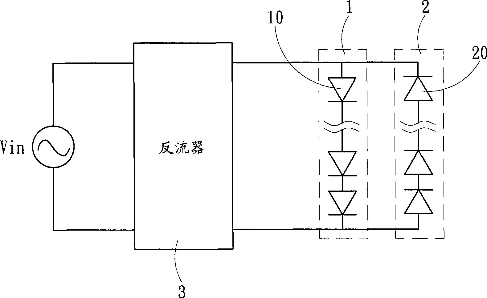
[0021] see image 3 Shown is a schematic circuit diagram of a preferred embodiment of the present invention. The LED alternating current driving method of the present invention comprises the following steps:

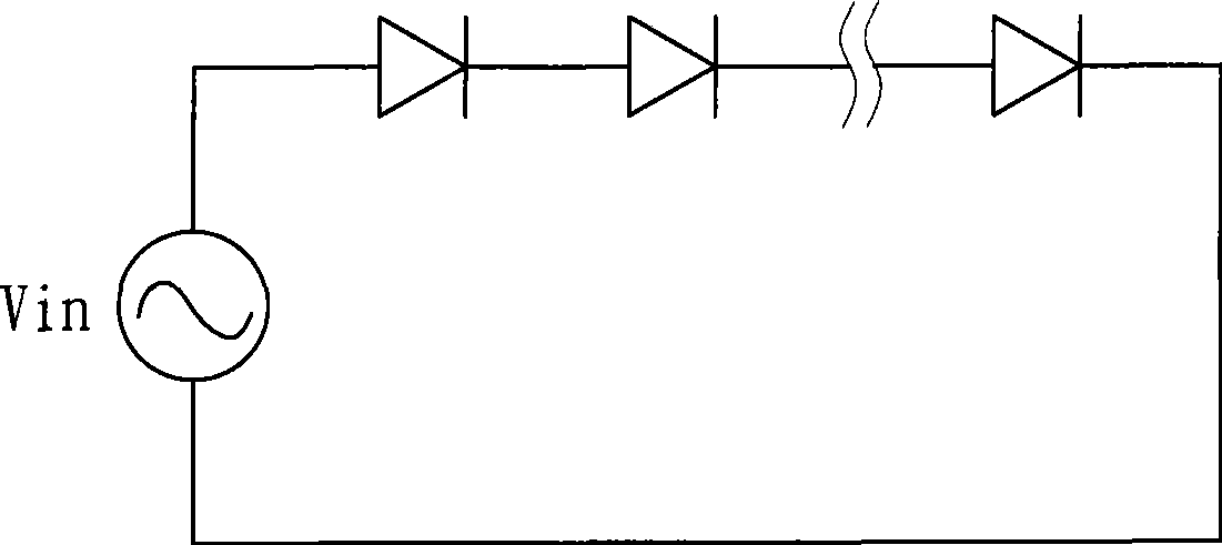
[0022] Steps to obtain AC power: Connect external power Vin to obtain AC sine wave signal S1 with positive and negative half-cycle waveforms (see Figure 4 As shown), the following assumes that the alternating current is 110 volts, 60 Hz frequency, that is, the lowest voltage value is 0 volts, and the highest voltage value is about 155 volts.

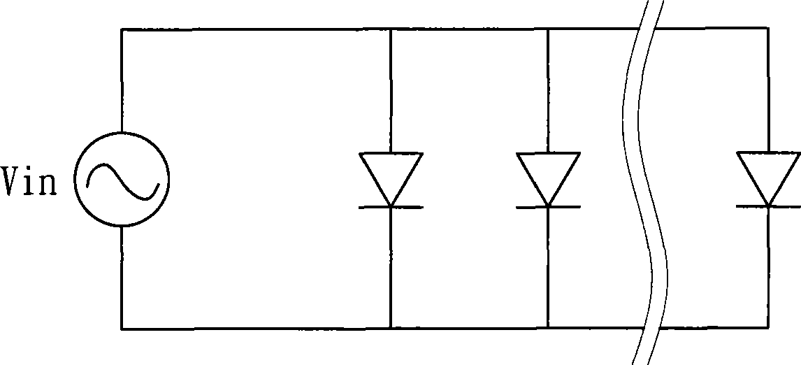
[0023] Light-emitting diode group setting step: it sets at least two first and second light-emitting diode groups 1 and 2 with opposite conduction directions and connected in parallel. In a preferred embodiment, each light-emitting diode group 1 and 2 is set to a plurality LEDs...


PUM


Abstract

An alternating current drive method of a light-emitting diode and working voltage thereof. The alternating current drive method of a light-emitting diode includes: an alternating current obtaining step, obtaining alternating current sine wave signal with positive and negative waves; an electric power modulation step, modulating the alternating current sine wave signal obtained by the alternating current obtaining step based on impedance values of at least two mutually paralleled first and second light-emitting diode groups with opposite conducting directions, modulating the positive half cycle waveform of the alternating current sine wave signal into a positive half cycle drive signal conforming to the operating region of the first light-emitting diode group, and modulating the negative half cycle waveform of the alternating current sine wave signal into a negative half cycle drive signal conforming to the operating region of the first light-emitting diode group; and an electric power drive step, driving the first light emitting diode group by the positive half cycle drive signal of the above electric power modulation step, and driving the second light emitting diode group by the negative half cycle drive signal, wherein, the first and second group of light-emitting diodes are driven in sequence by the positive and negative half cycle drive signals.

Description

technical field [0001] The invention relates to a driving method and its working voltage, in particular to a light-emitting diode alternating current driving method and its working voltage. Background technique [0002] Due to the advent of ultra-high-brightness LEDs and the maturity of white LED technology, products used in table lamps and projection lamps have gradually developed. The era of LED lighting has come. main light source. The traditional LED drive circuit converts the AC signal of the mains to DC and then drives the LED, but the conversion process will cause energy loss; for this reason, a circuit model that directly drives the LED with an AC signal has emerged. figure 1 Shown is the circuit mode for driving multiple LEDs in parallel, figure 2 Shown is a circuit mode of multiple LEDs driven in series, as disclosed in Taiwan Patent No. M310296, the light-emitting diode lamp group includes: a plug with a circuit board inside, which can convert AC power into DC ...

Claims


Application Information

Patent Timeline
Patent Type & Authority Applications(China)
IPC IPC(8): H05B37/02
Inventor 郑英彰刘士弘
Owner ZIPPY TECH
Why Eureka
Try Eureka