Installation of devices in a metal enclosure comprising two half-spacers for removal

A technology for installing equipment and metal casings, which is applied to the installation of switchgear with metal casings, the installation of busbars, and the installation of cables. It can solve the problem of expensive configuration and achieve the effect of reducing costs.

Inactive Publication Date: 2009-04-08
ALSTOM TECH LTD
View PDF2 Cites 0 Cited by
  • Summary
  • Abstract
  • Description
  • Claims
  • Application Information

AI Technical Summary

Problems solved by technology

This configuration is also very expensive

Method used


Image

  • Installation of devices in a metal enclosure comprising two half-spacers for removal
  • Installation of devices in a metal enclosure comprising two half-spacers for removal
  • Installation of devices in a metal enclosure comprising two half-spacers for removal

Examples


Embodiment Construction

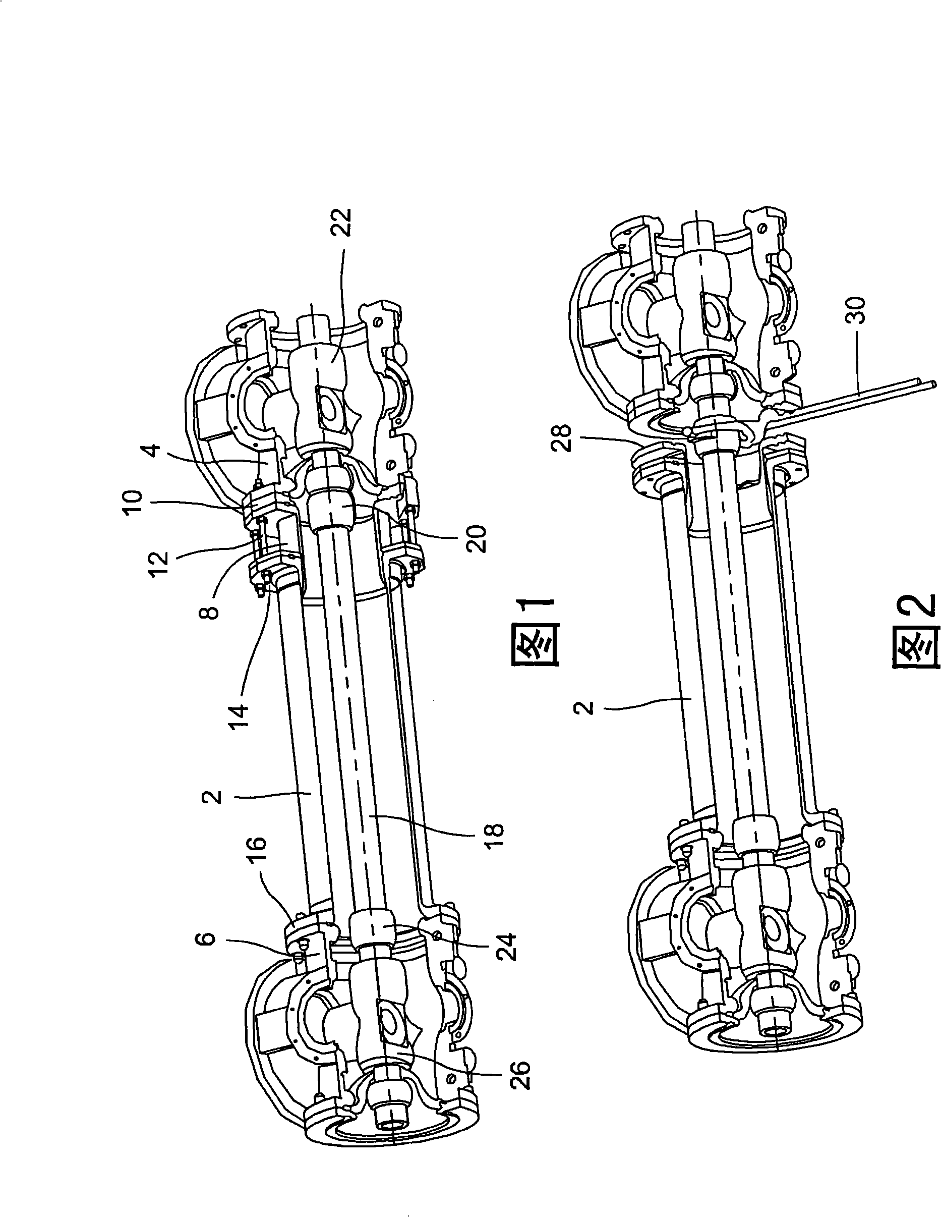
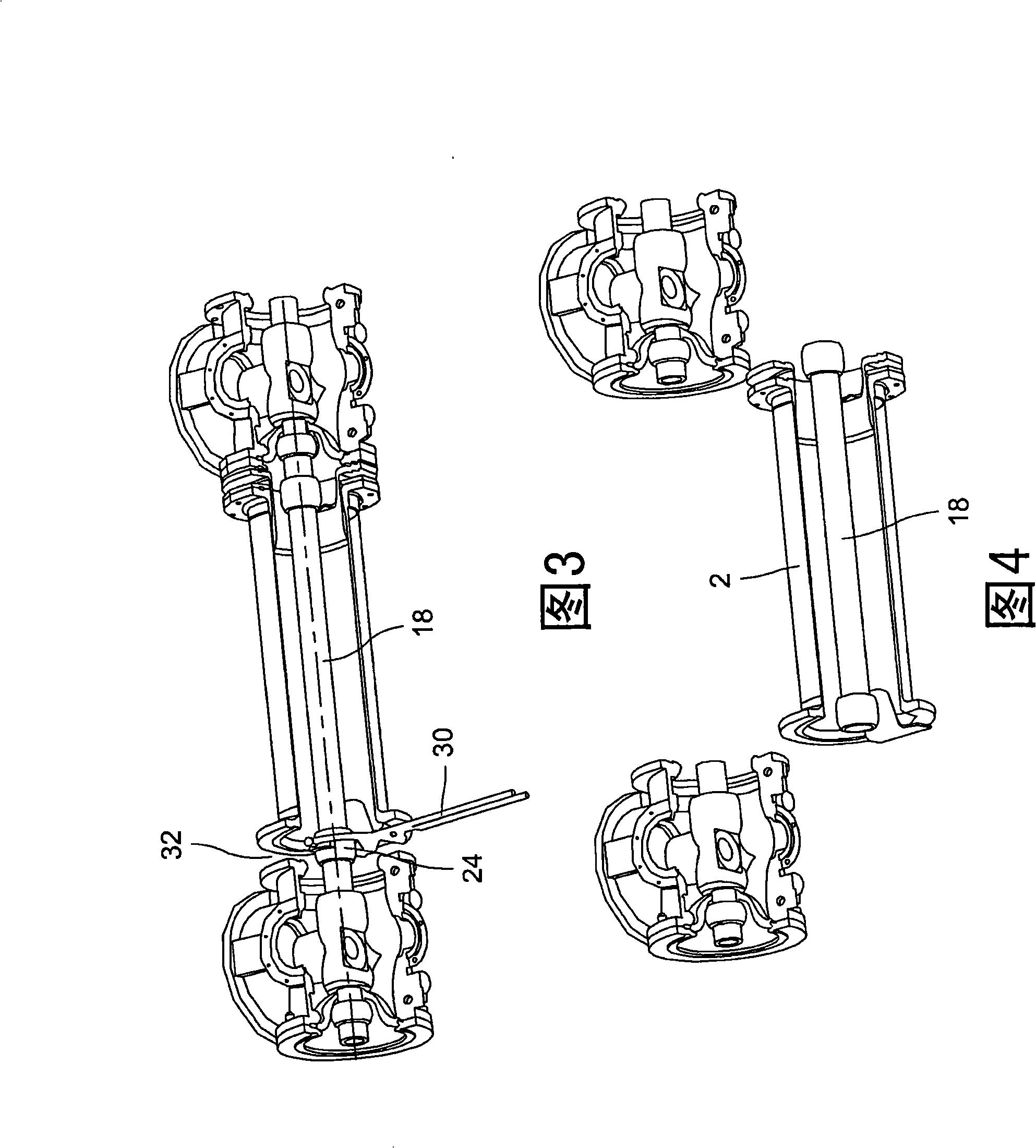
[0025] Figure 1 shows a mounting device in a metal enclosure comprising several parts with a longitudinal axis. These parts consist of the part to be removed 2 , the first adjacent part 4 and the second adjacent part 6 , respectively. In order to be able to remove the part 2 to be removed, this part comprises a telescoping sleeve 8 . The telescoping sleeve is held fixed to the flange 10 of the first adjacent part 4 by screw means 12 which are screwed onto the sleeve part 14 of the part 2 to be removed. At the other end of the part 2 to be removed, this part 2 is joined to a second adjacent part 6 via a flange 16 . The conductive rod 18 is placed axially inside the part 2 to be removed. The conductive rod 18 is joined at its first end by a nut 20 to an electrical device 22 mounted in the first adjacent part 4, while at its second end it is connected by a nut 24 to a second electrical device located in the second adjacent part. equipment26.

[0026] In Fig. 2, the screw 12 h...


PUM


Abstract

An installation apparatus includes a plurality of components(40, 42) with longitudinal axis, wherein, the components contain components (40) that will be dismantled, and adjacent parts (42); the components has flanges (44,46), and a removable rod (48) is placed in the axial direction of the components (40,42). A device for dismantling the components that will be dismantled comprises a first semi-interval piece (50) and a second semi-interval piece (52), each semi-interval piece having a horizontal surface and an inclined surface. The horizontal surfaces are respectively in junction with the flanges of the components that will be dismantled and the flanges (44, 46) of the adjacent parts. The inclined surfaces are arranged facing to each other, and are complementary to each other, so that the horizontal surfaces are parallel to each other.

Description

technical field [0001] The invention relates to a method of dismantling an element forming part of an electrical equipment installation inside a metal enclosure, said installation comprising a plurality of parts having a longitudinal axis. [0002] The invention also relates to a mounting device in a metal housing comprising a plurality of parts with a longitudinal axis, said parts including the part to be removed and adjacent parts, each said part having a flange, the removable rod axially arranged in In said component, the mounting device comprises dismantling means for dismantling the component to be dismantled. Background technique [0003] In this type of equipment, a shielded metal enclosure and conductors are placed next to each other in a continuous fashion such that the main current flows in the conductor and the current returns in the metal enclosure. [0004] Due to maintenance requirements, it must be possible in some cases to remove parts of the shielded switch...

Claims


Application Information

Patent Timeline
Patent Type & Authority Applications(China)
IPC IPC(8): H02B3/00H02B13/02H02G5/06
CPCH02G5/063H02B3/00
Inventor B·热洛斯C·雷什
Owner ALSTOM TECH LTD
Why Eureka
Try Eureka