
Two-wire system light-adjustable LED controller

A LED controller and two-wire technology, which is applied in the field of two-wire dimmable LED controllers, can solve the problems of inconvenient operation, inability to install directly, dimming, etc., and achieve the effect of good linearity of dimming control

Inactive Publication Date: 2009-04-08
梁莉丽
View PDF0 Cites 40 Cited by
  • Summary
  • Abstract
  • Description
  • Claims
  • Application Information

AI Technical Summary

Problems solved by technology

Since LED lighting is still an excessive lighting product, its driving mode is driven by constant current, which makes the dimming of LED cannot be dimmed by adjusting the voltage at both ends of it, so the control of the circuit still needs to be solved. Not fully compatible with current wiring
At present, the dimming of LEDs is dimmed by PWM pulses with a relatively high frequency, so the light source of LED lighting has not only two power lines, but also a dimming port, while traditional incandescent bulbs and halogen lamps are in the other. A thyristor dimmer is connected in series in front of the power line, and the dimming is performed by adjusting the effective voltage value of the load through front-cut phase or back-cut phase dimming, so the traditional dimming circuit is not compatible with the LED dimming method And direct installation; because LED lighting is a low-voltage power supply, in addition to the constant current source in the LED lamp body, there is also an AC-DC conversion power supply outside. If it is made into an LED dimming system with dimming function, it must be drawn from the LED lamp body. Two power lines and one dimming line, this operation is very inconvenient, there is no such lighting body on the market, such as MR16 is a light body with only two connectors, and it has dimming function, LED can do Just like MR16, there are only two terminals and the function of dimming will become the only way for the development of LED lighting

Method used


Image

  • Two-wire system light-adjustable LED controller
  • Two-wire system light-adjustable LED controller
  • Two-wire system light-adjustable LED controller

Examples


Embodiment Construction

[0028] The present invention will be further described below in conjunction with the accompanying drawings and specific embodiments.

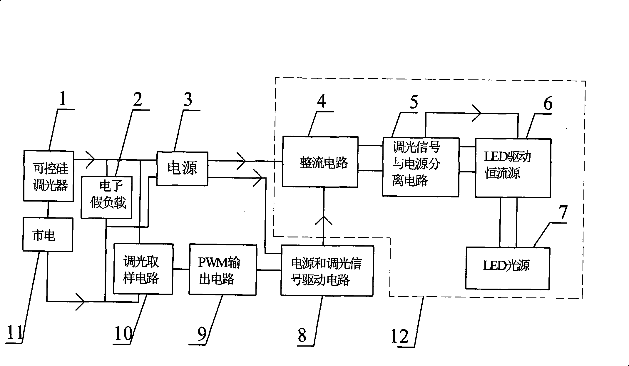
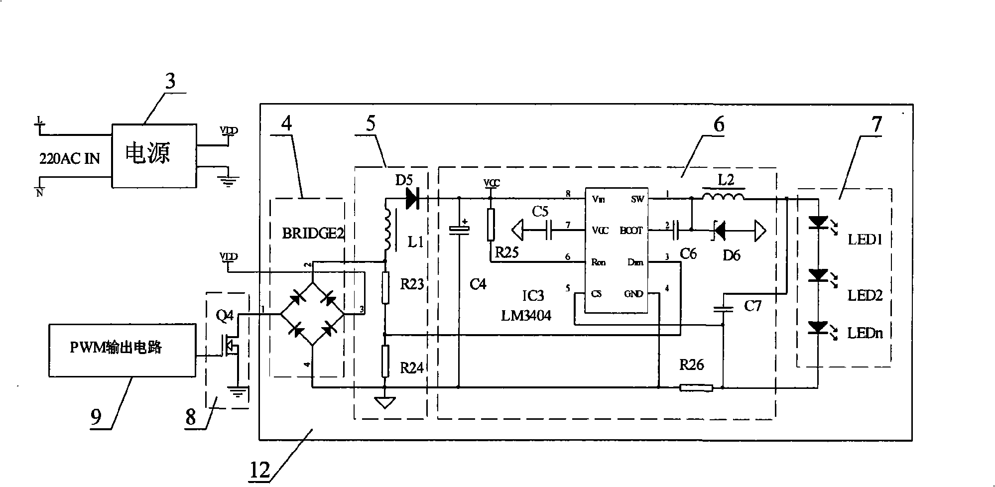
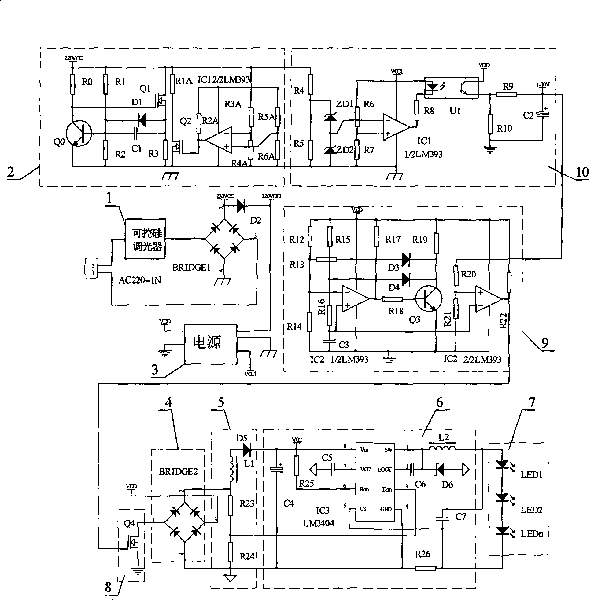
[0029] Such as figure 1 Shown, is the schematic block diagram of the circuit of the present invention, and it comprises: thyristor dimmer (1), electronic dummy load (2), power supply (3), rectifier circuit (4), dimming signal and power separation circuit (5 ), LED drive constant current source (6), LED light source (7), power supply and dimming signal drive circuit (8), PWM output circuit (9), dimming sampling circuit (10), dimmable two-wire LED lamp body(12);

[0030] The dimmable two-wire LED lamp body (12) includes a rectifier circuit (4), a dimming signal and power supply separation circuit (5), an LED driving constant current source (6), and an LED light source (7);

[0031] Its connection relationship: the mains (11) is divided into three circuits through the output of the thyristor dimmer (1), the first circuit is connected to the elec...


PUM


Abstract

The invention discloses a two-wire tunable optical LED controller which comprises an electronic fictitious load, a light-adjusting and sampling circuit, a power supply and light-adjusting signal drive circuit, a PWM output circuit, a rectification circuit in a tunable optical LED lamp body, a light-adjusting signal and power supply separating circuit, an LED drive constant current source and an LED light source. A PWM signal modulates a power supply through the power supply and light-adjusting signal drive circuit and combines an LED power supply source and a light-adjusting signal into the power supply containing light-adjusting information to be sent to the tunable optical LED lamp body. The rectification circuit in the lamp body processes the power supply containing the light-adjusting information for pole changing. The changed power supply containing the light-adjusting information is processed so as to separate the light-adjusting signal from the power supply by the light-adjusting signal and power supply separating circuit, the separated light-adjusting signal is sent to a light adjusting end of the LED drive constant current source, and the separated power supply is sent to the LED drive constant current source to supply power. The two-wire tunable optical LED controller has very wide application prospect with respect to the two-wire LED light adjustment.

Description

Technical field [0001] The present invention relates to a dimming controller, more specifically, to a two-wire dimmable LED controller. Background technique [0002] At present, the dimming object of the light is generally an incandescent lamp or a halogen lamp, and their dimming method is to add a silicon controlled rectifier dimmer to the front end to dim it, which is a direct high-voltage two-wire system. Dimming is a more traditional method of dimming. With the emergence of low-power and energy-saving LEDs, LEDs have low-voltage energy-saving, good spectrum, pure color, high luminous efficiency, no ultraviolet radiation, etc. These many advantages of LEDs make them actively promoted. Now they have become popular in commercial lighting. Begin to gradually replace ordinary light sources. Since LED lighting is still an excessive lighting product, its driving mode is driven by constant current, which makes the dimming of LED cannot be dimmed by adjusting the voltage at bot...

Claims


Application Information

Patent Timeline
IPC IPC(8): H05B37/02
Inventor 梁莉丽
Owner 梁莉丽
Learn More