Motor speed control circuit

A speed control, speed voltage technology, applied in the control system, motor control, electrical components, etc., can solve the problems of motor speed increase, temperature rise, etc.

Inactive Publication Date: 2009-04-15
SANYO ELECTRIC CO LTD +1
View PDF3 Cites 12 Cited by
  • Summary
  • Abstract
  • Description
  • Claims
  • Application Information

AI Technical Summary

Problems solved by technology

Also, even when the duty ratio of the H level of the PWM signal is fixed, the rotation speed of the motor increases as the temperature rises.

Method used


Image

  • Motor speed control circuit
  • Motor speed control circuit
  • Motor speed control circuit

Examples


no. 1 approach

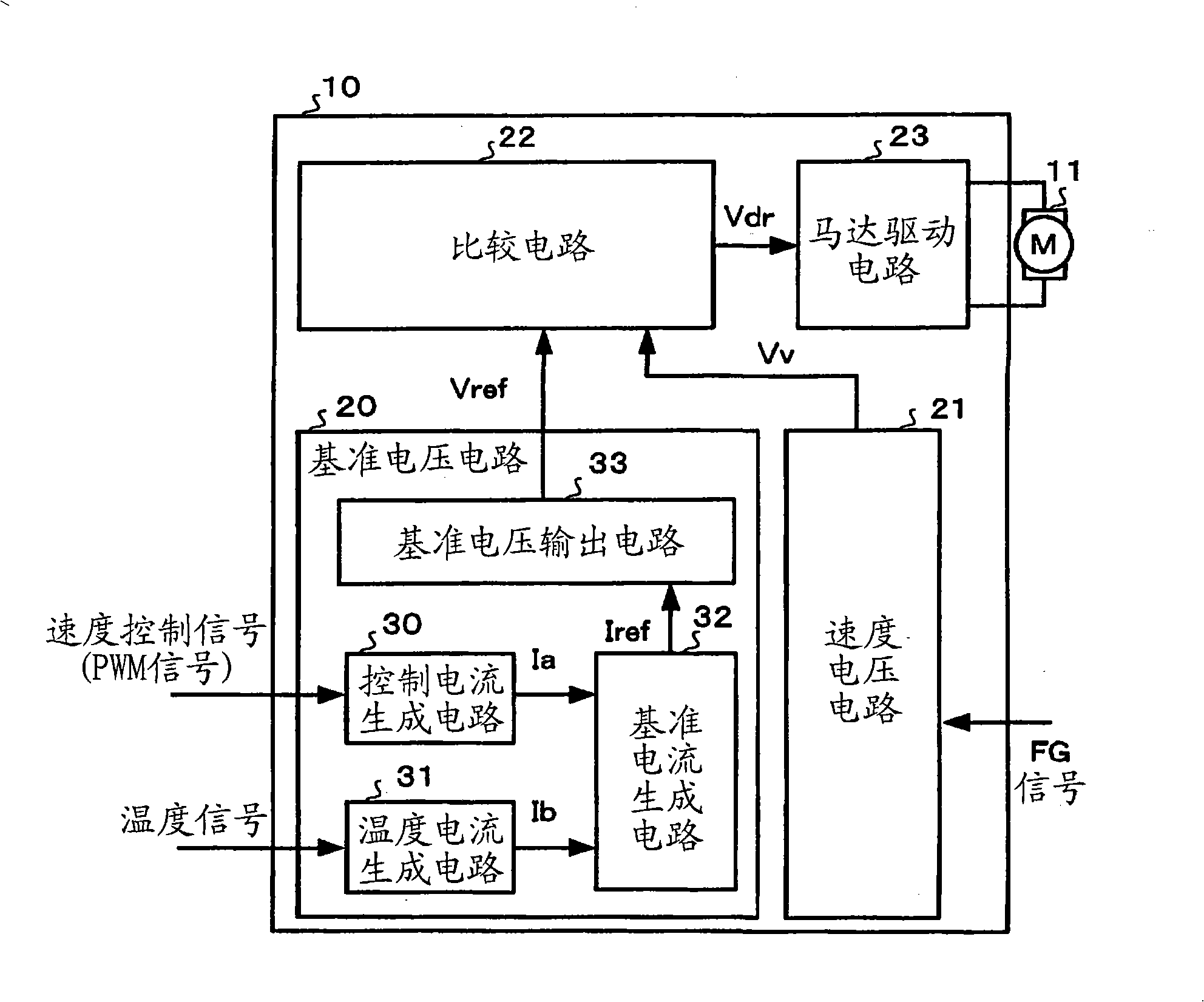
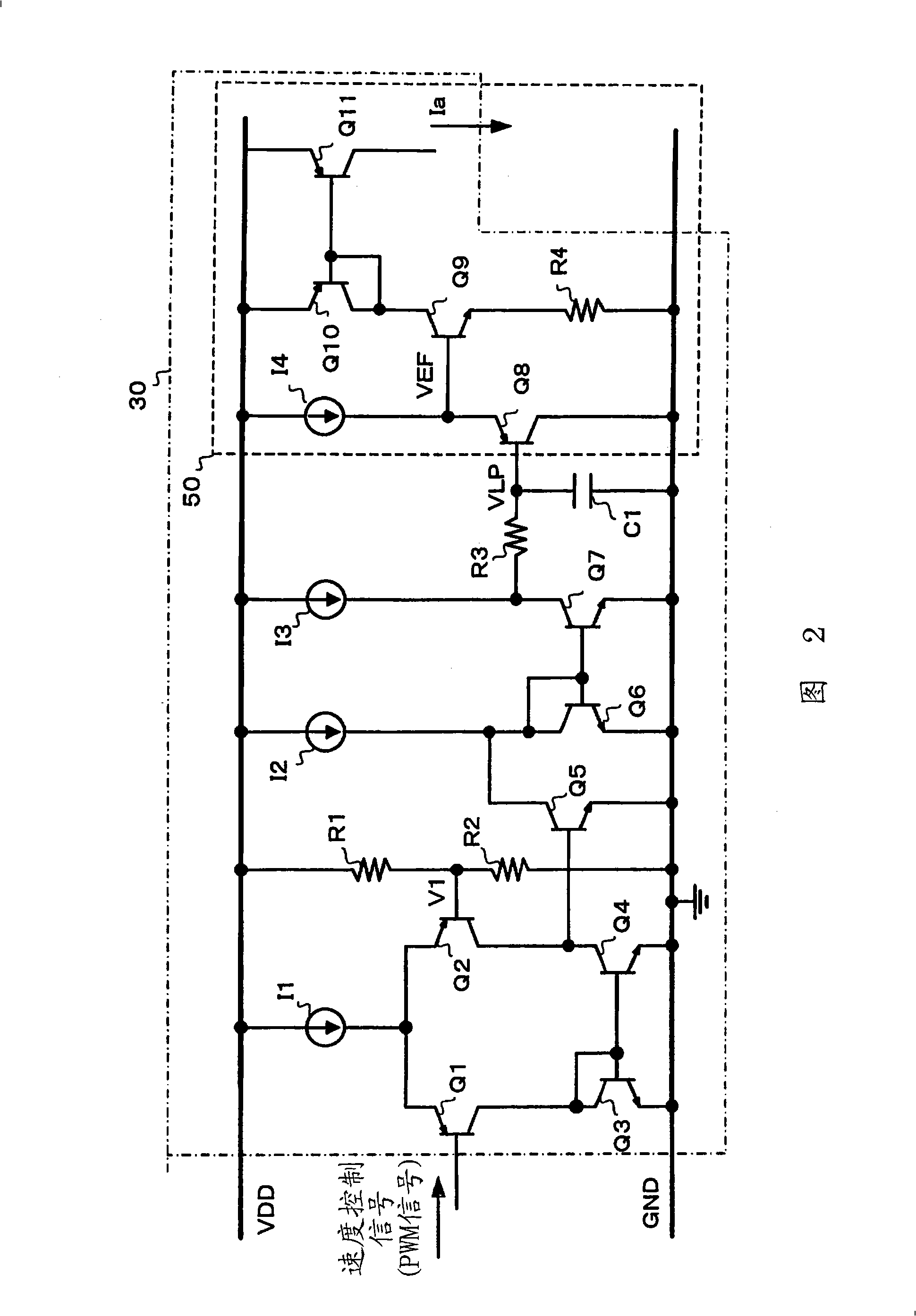
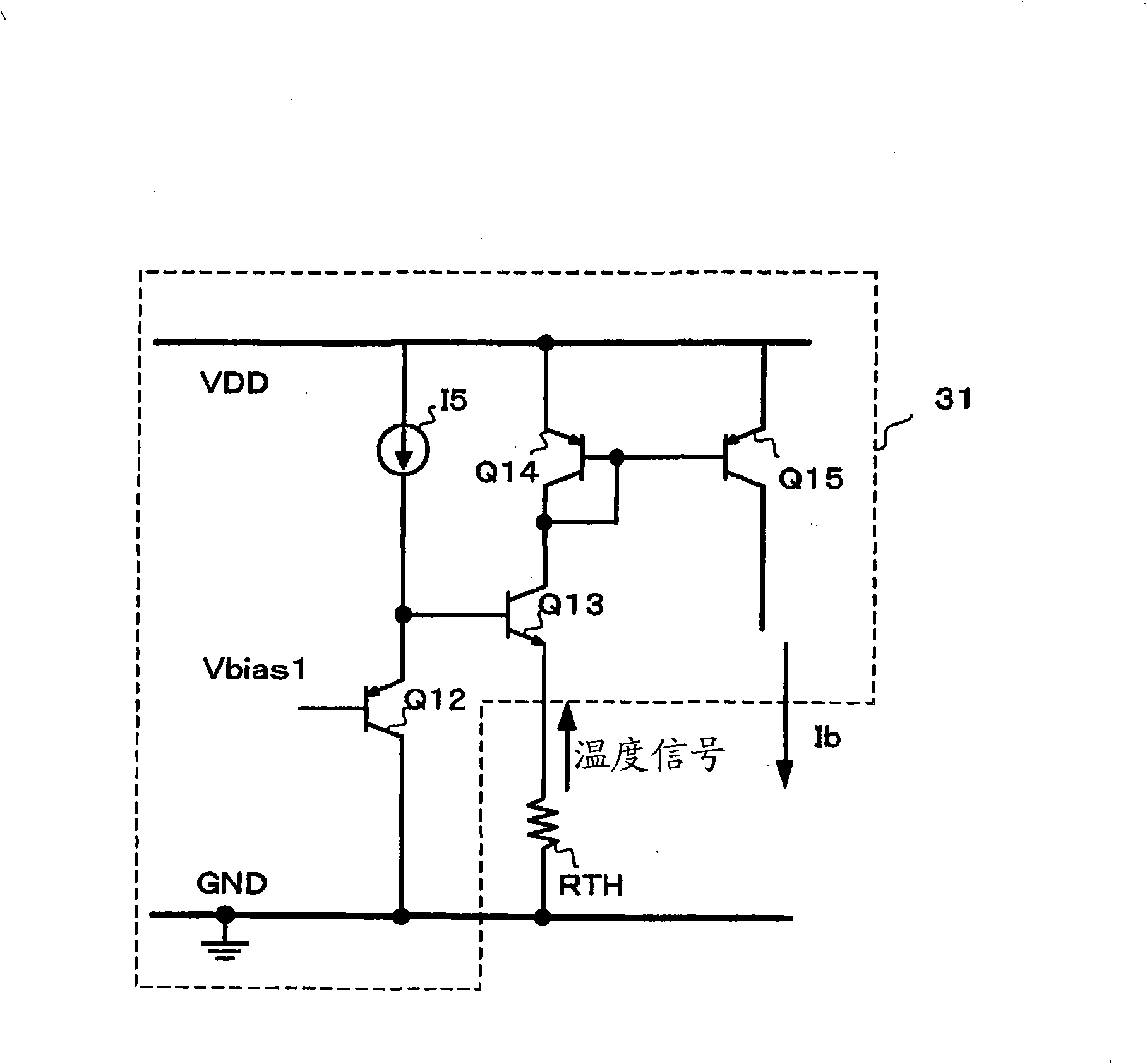
[0032] figure 1 It is a figure which shows the structure of the motor speed control circuit 10 which is 1st Embodiment of this invention. FIG. 2 is a diagram illustrating an embodiment of the control current generation circuit 30 . image 3 It is a diagram showing an embodiment of the temperature current generating circuit 31 to which the thermistor RTH is connected. FIG. 4 is a diagram illustrating an embodiment of the reference current generating circuit 32 . Figure 5 It is a diagram showing an embodiment of the reference voltage output circuit 33 . FIG. 6 is a diagram showing an embodiment of the speed voltage circuit 21 . FIG. 7 is a diagram showing one embodiment of the comparison circuit 22 . refer to figure 1 The motor speed control circuit 10 of the first embodiment will be described with reference to FIG. 7 .

[0033] The motor speed control circuit 10 controls the speed of the motor 11 according to the speed control signal corresponding to the target rotatio...

no. 2 approach

[0070] Figure 10 It is a figure which shows the structure of the motor speed control circuit 100 which is 2nd Embodiment of this invention. FIG. 11 is a diagram illustrating an embodiment of the reference voltage circuit 200 . Figure 12 It is a diagram showing an embodiment of the temperature current generating circuit 300 to which the thermistor RTH is connected. FIG. 13 is a diagram showing an embodiment of the speed voltage output circuit 310 . refer to Figure 10 ~ Figure 1 3. The motor speed control circuit 100 of the second embodiment will be described.

[0071] The motor speed control circuit 100 is a circuit for controlling the rotation speed of the motor 11 based on a speed control signal corresponding to the target rotation speed of the motor 11, a temperature signal corresponding to the temperature, and a speed signal corresponding to the actual rotation speed of the motor 11 input from the microcomputer. , consists of a reference voltage circuit 200 , a speed...


PUM


Abstract

A motor speed control circuit includes: a voltage generating circuit configured to output a reference voltage corresponding to a target rotation speed of a motor and a speed voltage corresponding to a rotation speed of the motor, and change either the reference voltage or the speed voltage according to a temperature; a comparison circuit configured to compare the speed voltage with the reference voltage; and a driving circuit configured to drive the motor so as to match a level of the speed voltage to a level of the reference voltage, based on a comparison result from the comparison circuit.

Description

technical field [0001] The present invention relates to motor speed control circuits. Background technique [0002] In recent years, integrated circuits such as a CPU (Central Processing Unit: central processing unit) used in electronic equipment have gradually increased their heat generation as their operating speeds increase. Since the heat generated by the CPU increases, causing problems such as overheating in the CPU, electronic devices are generally provided with fans for cooling the CPU. [0003] Figure 16 An example of a block diagram of a motor speed control circuit that controls the rotation speed of a fan motor for cooling a CPU is shown in . Specifically, a speed control signal from a microcomputer or the like corresponding to the target rotational speed of the motor 500 and a temperature signal from a thermistor corresponding to the temperature around the CPU are input to the reference voltage circuit 700, and the output is in accordance with the speed control ...

Claims


Application Information

Patent Timeline
Patent Type & Authority Applications(China)
IPC IPC(8): H02P29/00H02P29/60
Inventor 原岛崇扇野广一郎
Owner SANYO ELECTRIC CO LTD
Why Eureka
Try Eureka