Air compressor with variable speed motor

a variable-speed motor and air compressor technology, applied in the direction of motor parameters, piston pumps, pump control, etc., can solve the problems of confusing the existence of both the tank pressure and line pressure gauges for a new user, confusing the variable knob and fixed rate spring, and difficulty in adjusting to a desired output pressur

Inactive Publication Date: 2006-03-02
DEVILBISS AIR POWER COMPANY
View PDF42 Cites 101 Cited by
  • Summary
  • Abstract
  • Description
  • Claims
  • Application Information

AI Technical Summary

Benefits of technology

[0019] In an embodiment, the signal provided by the tool is a resistance provided by the tool in a circuit that includes a resistor. The air compressor utilizes a lookup table to determine the necessary operating functions

Problems solved by technology

Although conventional air compressors work well for their intended purpose, the existence of both the tank pressure and line pressure gauges may be confusing to a new user.
The variable knob and fixed rate spring may also be confusing, and may be difficult to adjust to a desired output pressure.
Another problem inherent in the design of the mechanical gauges is that the gauges are susceptible to vibration, which all air compressors have.
Vibration sometimes makes the mechanical pressure gauges on conventional air compressors difficult to read.
One downside to electrical air compressors is that they must be designed to operate at conventional circuit levels.
Designing a conventional air compressor within the l

Method used


Image

  • Air compressor with variable speed motor
  • Air compressor with variable speed motor
  • Air compressor with variable speed motor

Examples


Embodiment Construction

[0041] In the following description, various embodiments of the present invention will be described. For purposes of explanation, specific configurations and details are set forth in order to provide a thorough understanding of the embodiments. However, it will also be apparent to one skilled in the art that the present invention may be practiced without the specific details. Furthermore, well-known features may be omitted or simplified in order not to obscure the embodiment being described.

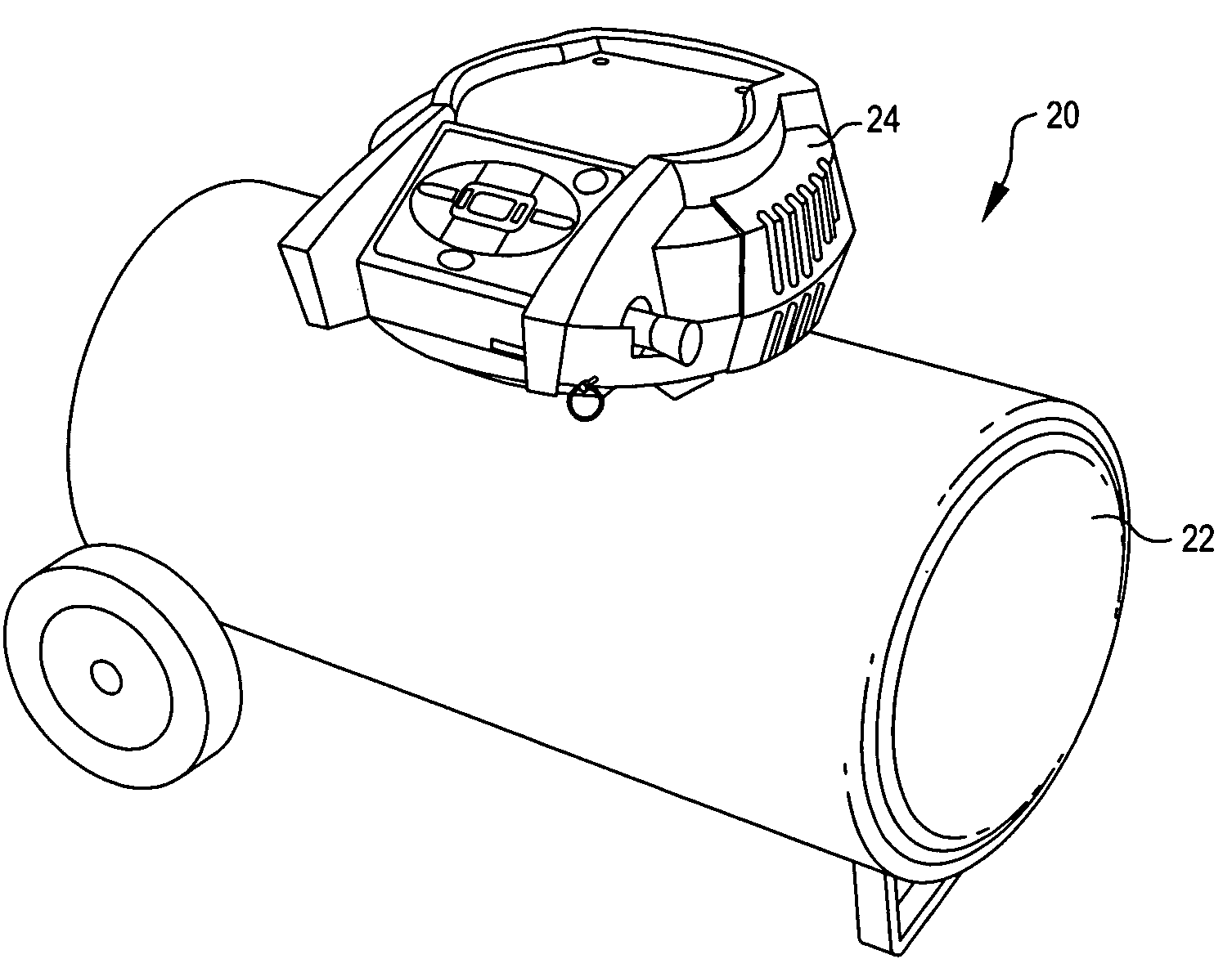
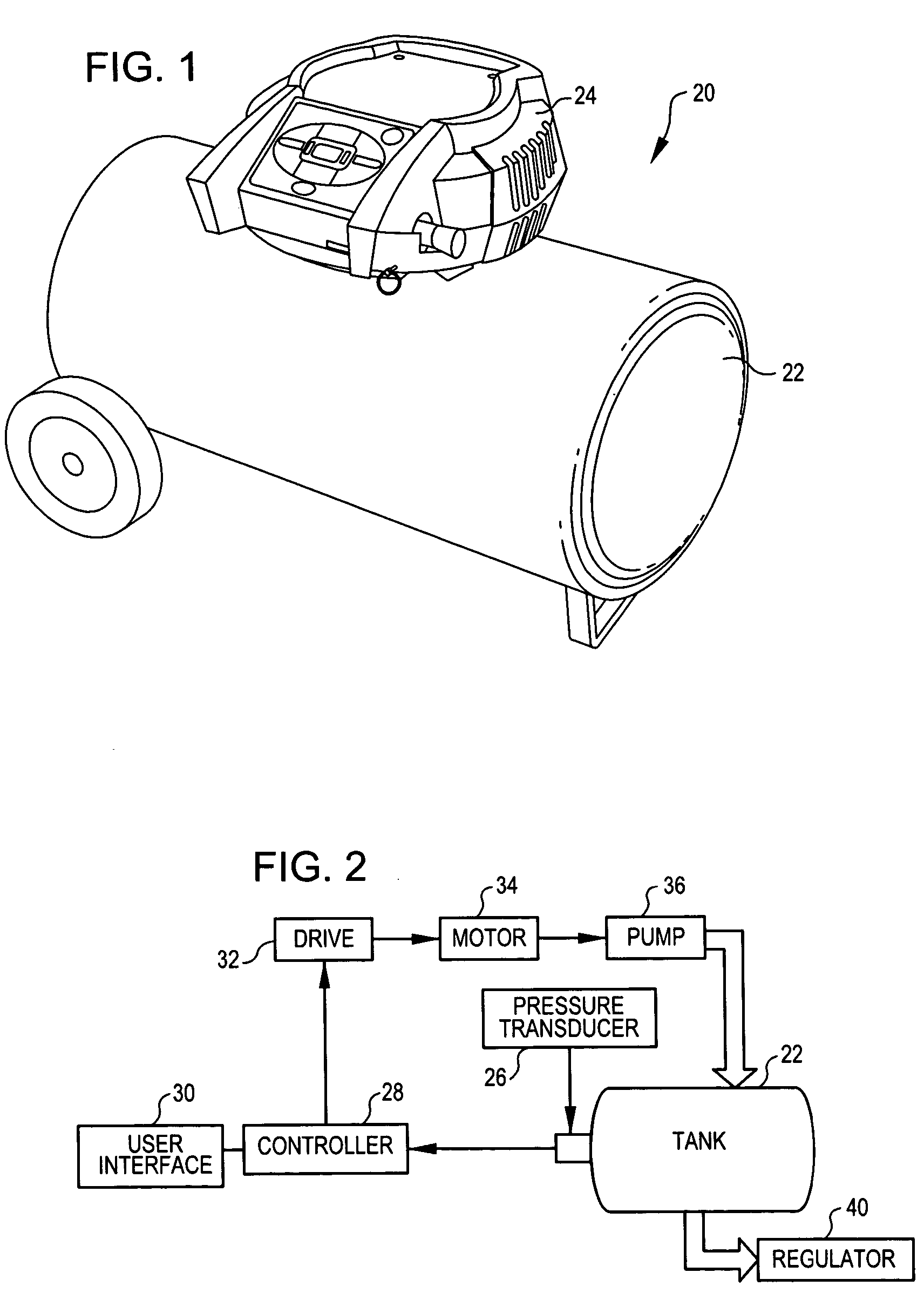
[0042] Referring now to the drawings, in which like reference numerals represent like parts throughout the several views, FIG. 1 shows an air compressor 20 incorporating aspects of the present invention. The air compressor 20 includes a tank 22 with a shroud 24 mounted thereon. Internal components are mounted in the shroud 24, one embodiment of which is shown diagrammatically in FIG. 2.

[0043] The tank 22 for the air compressor 20 is, for example, a 20-gallon cylindrical compressor tank. The tan...


PUM


Abstract

An air compressor utilizing an electronic control system. A pneumatically controlled regulator is provided for controlling output pressure for an air compressor. Digital gauges are provided on the air compressor to replace conventional mechanical gauges. A variable speed motor is used, which in turn varies the speed of the pump. Tools are provided for an air compressor that are capable of transmitting a signal to the air compressor indicating a desired pressure and/or motor speed at which the air compressor is to operate.

Description

REFERENCE TO RELATED APPLICATIONS [0001] The present invention is related to United States Patent Applications entitled “AIR COMPRESSOR TOOLS THAT COMMUNICATE WITH AN AIR COMPRESSOR” (Attorney Docket No. 306364) and “AIR COMPRESSOR UTILIZING AN ELECTRONIC CONTROL SYSTEM” (Attorney Docket No. 306321),” having at least one common inventor, filed concurrently herewith, and hereby incorporated by reference in their entireties. TECHNICAL FIELD OF THE INVENTION [0002] The present invention relates generally to power tools, and more particularly to air compressors. BACKGROUND OF THE INVENTION [0003] Air compressors are becoming commonplace in home workshops. In general, an air compressor is a machine that decreases the volume and increases the pressure of a quantity of air by mechanical means. Air thus compressed possesses great potential energy, because when the external pressure is removed, the air expands rapidly. The controlled expansive force of compressed air is used in many ways and...

Claims


Application Information

Patent Timeline
IPC IPC(8): F04B49/06F04B17/00
CPCF04B41/02F04B2203/0209F04B49/022
Inventor BECKMAN, KURTGRABER, TOM
Owner DEVILBISS AIR POWER COMPANY
Why Eureka
Try Eureka