Paying out and retracting an electric power cord

a technology for electric power cords and devices, which is applied in the field of can solve the problems of comparatively complicated devices for paying out and retracting electric power cords according to u.s. pat. no. 4,736,826

Inactive Publication Date: 2013-11-05
KONINK PHILIPS ELECTRONICS NV
View PDF6 Cites 0 Cited by
  • Summary
  • Abstract
  • Description
  • Claims
  • Application Information

AI Technical Summary

Benefits of technology

[0009]When the cord winding reel (said first cord winder member) is driven by the motor through the slipper clutch and the one-way clutch, the driving member (said second cord winder member) is driven by the motor at a speed proportional to the rotational speed of the motor. The speed of the driving member thus determines the displacement speed of the cord. When the cord is refracted, the driving member moves the cord in the direction of the reel, and the reel is driven by the motor through the slipper clutch at a relatively high speed, so that the slipper clutch is slipping while the cord is wound onto the reel. When the motor drives the driving member in the other direction, the cord is pulled by the driving member from the reel, during which the one-way clutch enables the reel to perform the required rotation. The motor accordingly drives the input of the one-way clutch at a relatively high speed, and the one-way clutch allows a free rotation of the reel at a lower speed.
[0010]In a preferred embodiment, the motor is connected with driving force to the drive element (said second cord winder member) via the slipper clutch for driving the drive element in the cord paying out direction, the ratio of the rotational speed of the reel to the rotational speed driving the slipper clutch (i.e. the input speed of the slipper clutch) being such that the slipper clutch is always slipping during unwinding of the cord from the reel. The one-way clutch is present in the connection between the motor and the drive element, so that the drive element (and thus the cord) is free to move in the retraction direction more slowly than the driving speed caused by the motor.
[0012]Preferably, the drive element comprises a drive wheel for engaging the cord and a freely rotating support wheel for pushing the cord against the drive wheel. The drive wheel may have a circumferential groove such that the support wheel pushes the cord into the groove so as to engage the cord firmly without slippage.
[0013]It may be required that the drive element exerts a certain force on the cord when the cord is retracted by the reel. Therefore, in a preferred embodiment, adjustable means are present for pressing the support wheel against the drive wheel, so that the resistance of the drive element can be varied.
[0015]When the device is incorporated in a mobile apparatus, such as a robotic vacuum cleaner, the cord has to be paid out and retracted in a controlled manner. The travelling path of the mobile apparatus can be measured and / or calculated in that the movement of the wheels of the apparatus is sensed and / or the surroundings of the apparatus are observed by a camera or the like. The paying out or retracting speed of the cord can thus be controlled in that the rotational speed of the electric motor is controlled. In a preferred embodiment of the invention, a sensor is present for measuring the paying out speed and the retraction speed of the cord, so that the desired cord displacement speed can be compared with the instantaneous displacement speed, and the motor can be controlled on the basis of the difference between these two speeds.

Problems solved by technology

The device for paying out and retracting the cord according to U.S. Pat. No. 4,736,826 is comparatively complicated, in particular owing to the presence of two electric motors for driving the cord winding reel and for driving the cord drive element, respectively, and owing to the presence of control means for controlling the speeds of both motors independently of each other.

Method used


Image

  • Paying out and retracting an electric power cord
  • Paying out and retracting an electric power cord
  • Paying out and retracting an electric power cord

Examples


Embodiment Construction

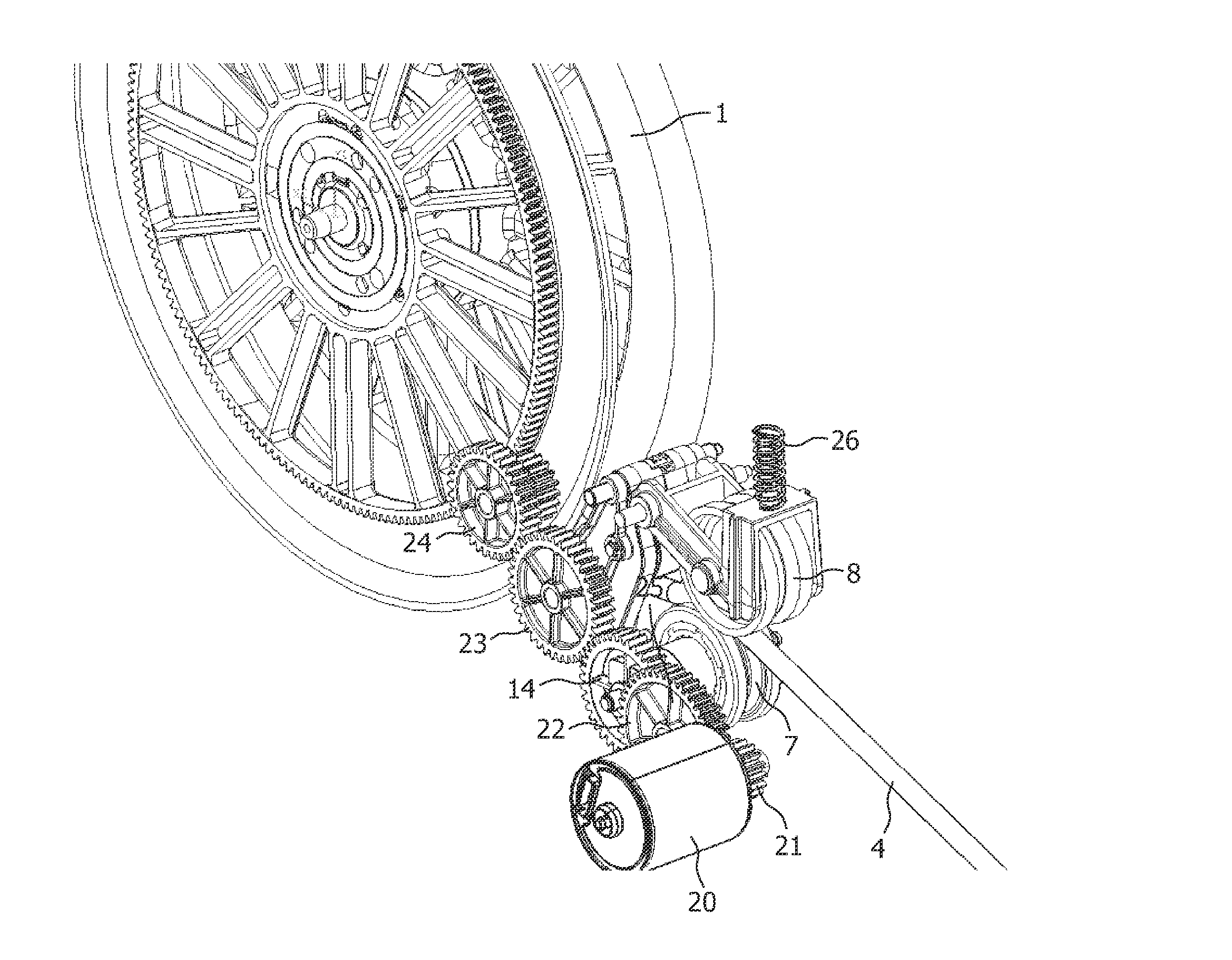
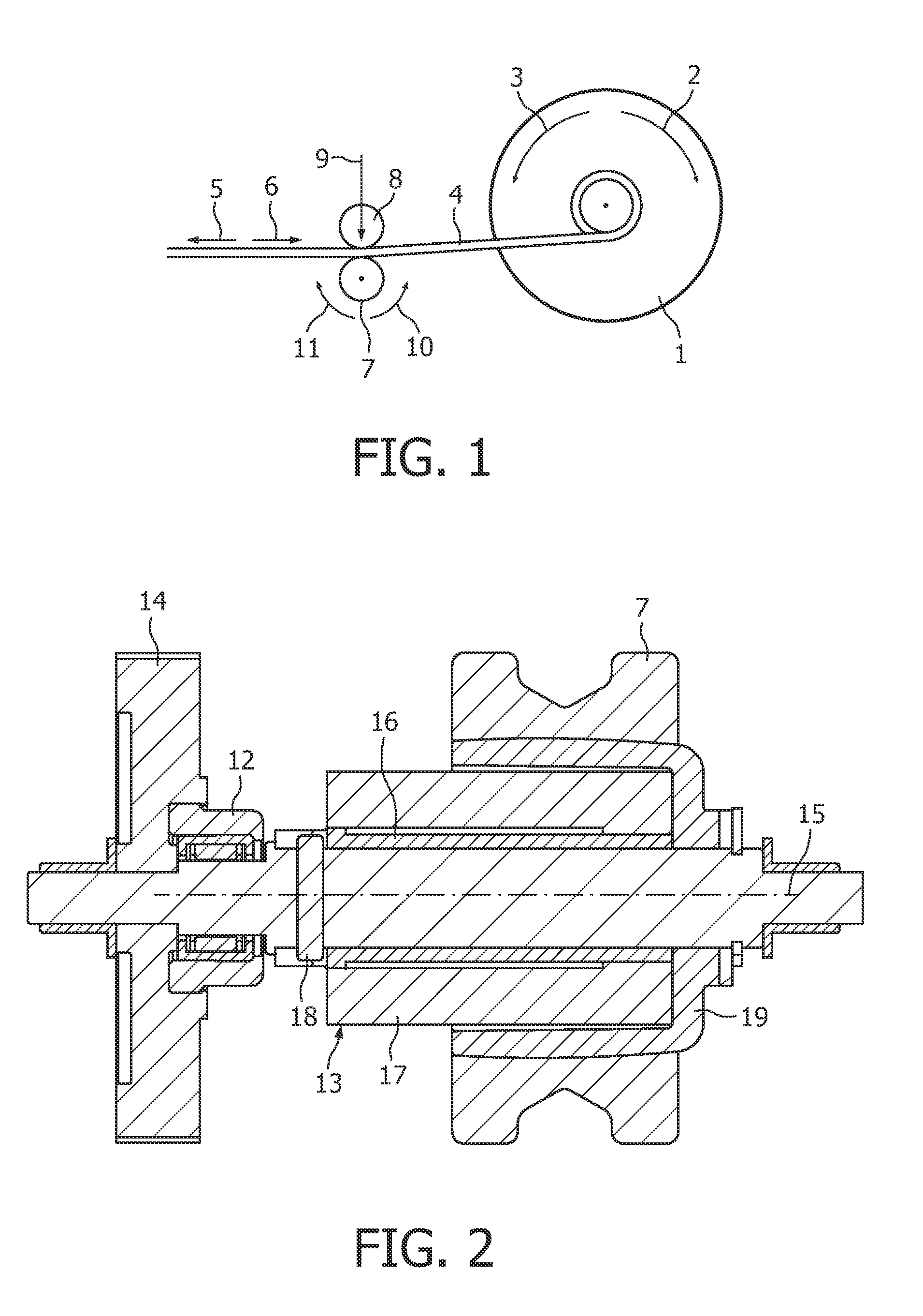
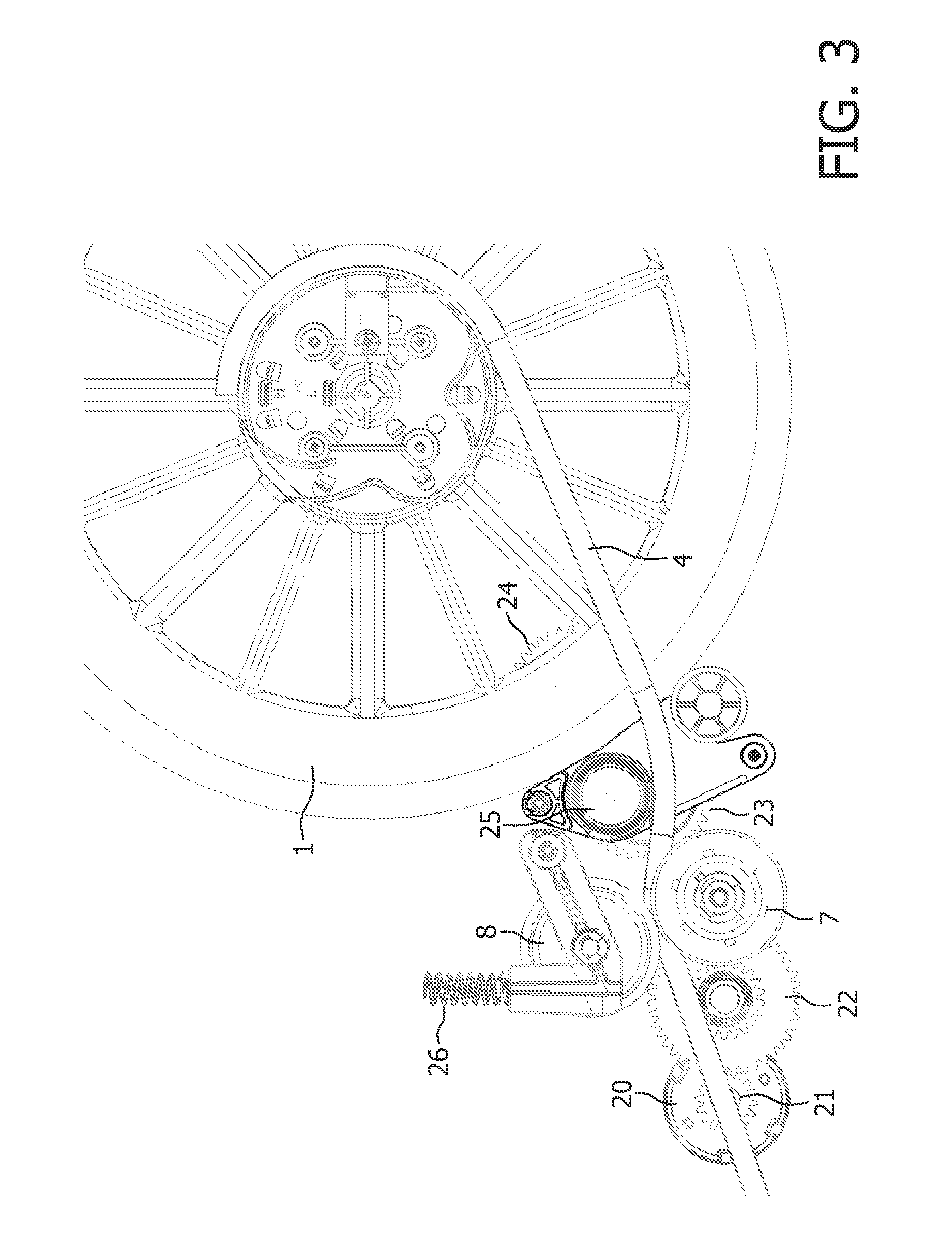
[0024]FIG. 1 shows a cord winding reel 1 that is driven by an electric motor (not shown) in the cord paying out direction (arrow 2) or in the cord retraction direction (arrow 3), such that the electric power cord 4 is unwinding or winding on the reel 1, respectively. Arrow 5 and arrow 6 indicate the displacement of the cord 4 in the paying out direction and in the retraction direction, respectively. A drive element 7, 8 is present for engaging the cord 4 at some distance from the reel 1. The drive element comprises a drive wheel 7 and a support wheel 8, the support wheel 8 pressing the cord 1 against the rotating surface of the drive wheel 7, as is indicated with arrow 9, so that there is no slip between the cord 4 and the drive wheel 7.

[0025]When the electric motor drives the reel 1 in the paying out direction (arrow 2), the cord 4 has to be pulled away from the cord winding reel 1 by the drive element 7, 8. In order to exert a predetermined pulling force on the cord 4, the drive e...


PUM


Abstract

A device for paying out and retracting an electric power cord (4) comprising two driven cord winder members, the first member being a cord winding reel (1) and the second member being a drive element (7, 8) for engaging the cord (4) at a distance from the reel (1). An electric motor (20) can drive one of the two cord winder members in two directions and is connected with driving force to the other cord winder member (7, 8) by way of a slipper clutch (13) and a one-way clutch (12).

Description

FIELD OF THE INVENTION[0001]The invention relates to a device for paying out and retracting an electric power cord, comprising an electric motor and two driven cord winder members, the first member being a cord winding reel and the second member being a drive element for engaging the cord at a distance from the reel, wherein the motor can drive one of the two cord winder members in two directions.BACKGROUND OF THE INVENTION[0002]Such a device is disclosed in U.S. Pat. No. 4,736,826. This publication describes a mobile robot remotely powered through an electric cord from a stationary console. The robot carries a cord managing arrangement which stores the cord and pays out or retracts the cord as needed. The arrangement lays down the cord under zero tension when the robot is outbound and reels it in as the robot returns. Thereby, the robot can follow a tortuous path without entangling the cord under or around obstacles. The cord is stored on the cord winding reel and is engaged by the...

Claims


Application Information

Patent Timeline
Patent Type & Authority Patents(United States)
IPC IPC(8): B65H75/48
CPCA47L9/26B65H51/10B65H75/42B65H75/4402B65H75/4484B65H75/4486H02G11/02B65H2701/34B65H75/34
Inventor VEENSTRA, AUKE-JANBALTUSSEN, HENRICUS WILHELMUS JOHANNES
Owner KONINK PHILIPS ELECTRONICS NV
Why Eureka
Try Eureka