Electromagnetic actuator device

a technology of actuators and actuators, applied in the direction of electromagnets, electrical devices, magnetic bodies, etc., can solve the problems of not being able to remove from the device of known art, and achieve the effect of compactness

Inactive Publication Date: 2015-08-25
ETO MAGNETIC GMBH
View PDF86 Cites 0 Cited by
  • Summary
  • Abstract
  • Description
  • Claims
  • Application Information

AI Technical Summary

Benefits of technology

[0004]The object of the present invention is therefore to create an electromagnetic actuator device in which a coil unit that can be energised surrounds a first yoke section of a stationary yoke unit, and armature means, controlled such that it can move relative to the yoke unit, interacting with an actuation partner, and which can be driven so as to execute an actuation movement, interact with a second yoke section of the yoke unit with the formation of the working air gap, with regard to improving a more compact, in particular also a more flexible mechanical implementation, thereby in particular to create the possibility of separating the coil unit from the working air gap, and to create the possibility of implementing an improved heat removal, or to allow heat to occur in a locally distributed manner (and thus less concentrated at one location).
[0010]In a particularly preferred configuration of the first aspect of the invention, namely of the design of an individual or a plurality of magnetic flux-conducting circuits in the yoke unit, wherein each of the flux-conducting circuits runs through the first yoke section (carrying the common coil), and also across a particular one of the air gaps assigned to one of the plurality of armature units, a magnetic flux resistance of the flux conducting agents of at least one of the magnetic flux-conducting circuits can be varied as a function of a magnetic flux that is flowing therein. This occurs in particular in that by a suitable configuration of an effective flux-conducting cross-section of these flux-conducting agents saturation occurs from a predetermined magnetic flux density, thus from this threshold the magnetic flux resistance is increased. The consequence of this effect is that a magnetic flux from the flux-conducting circuit concerned is displaced into another of the flux-conducting circuits; in this respect an armature movement can then be triggered or influenced.
[0015]By means of flux-conducting agents, suitably provided in accordance with a development of the invention in the form of suitable elements (which more preferably for example can be implemented as sheets, or a stack of sheets, which can beneficially be stamped out in the production process) it is possible to implement structures that are beneficially adapted to a particular deployment objective (i.e. a particular site of deployment and the installation conditions applying there). Thus it is for example in accordance with a development of the invention preferable to implement these flux-conducting elements as flat, i.e. plane elements, which further advantageously, for example, are provided on both sides of central axes of both the plurality of coil devices and also of the second yoke section (with the working air gap) for purposes of the flux-conducting connection of the same, such that in turn a simple arrangement that can be produced in a manner suitable for large scale production, nevertheless one that is optimised with regard to space utilisation comes into being (wherein here in particular design options also exist for undertaking thermal optimisations).

Problems solved by technology

Moreover the device of known art from this prior art also requires a not insignificant build space, wherein in addition heat removal from the device of known art is not without its problems.

Method used


Image

  • Electromagnetic actuator device
  • Electromagnetic actuator device

Examples


Embodiment Construction

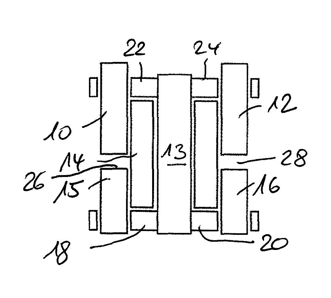
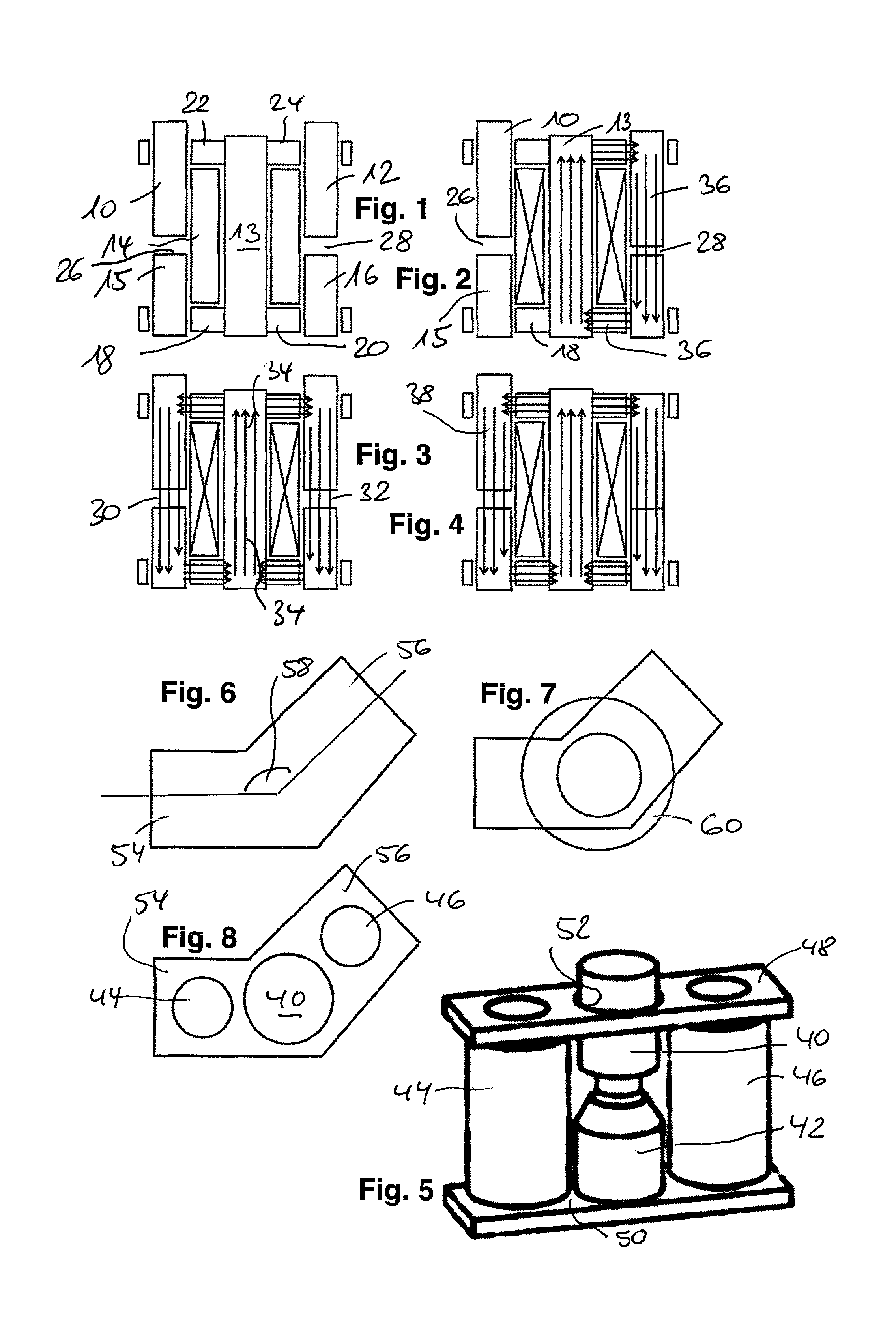
[0027]FIG. 1 illustrates in a schematic longitudinal sectional view an electromagnetic actuator device for purposes of driving two armature units 10, 12 by means of a common coil unit 14 provided centrally between the latter on a yoke section 13. Stated more precisely, as can be discerned schematically with the aid of the FIG. 1 diagram, the armature units 10, 12 respectively, represented in an elongated manner, are controlled such that they can move axially (in a direction of movement and drive at right-angles in the plane of the figure), wherein the armature units 10 and 12 interact with stationary yoke sections 15, 16 respectively and, for purposes of implementing corresponding flux-conducting circuits running jointly through the coil unit 14, which are controlled via flux-conducting connecting sections 18 to 24. Accordingly effective air gaps 26 and 28 respectively are formed for the armature units 10 and 12 respectively.

[0028]FIGS. 2 to 4 illustrate various operating states in ...


PUM

PropertyMeasurementUnit
angleaaaaaaaaaa
angleaaaaaaaaaa
magneticaaaaaaaaaa

Abstract

An electromagnetic actuator device, comprising a coil unit (14), which surrounds a first yoke section (13) of a stationary yoke unit and can be activated by energizing the coil unit; and armature elements (10, 12), which are guided so as to be movable relative to the yoke unit and which interact with an output-side actuating partner and which can be driven in order to perform an actuating movement. The armature elements interact with at least one second yoke section (15, 16) of the yoke unit to form an air gap (26, 28) for a magnetic flux produced by the activated coil unit.

Description

BACKGROUND OF THE INVENTION[0001]The present invention concerns an electromagnetic actuator device.[0002]Such a device is for example of known art from JP 2000 170951 A and concerns an electromagnetic actuator device for the implementation of a 3-way valve, in which, in a departure from conventional actuator technologies, which moreover are presupposed to be of known art, the coil winding does not surround the armature (or the related working air gap), rather the coil winding, in the form of an “outsourced” coil is laterally displaced relative to a longitudinal axis of armature movement (and a related air gap) and a magnetic flux transfer takes place to the armature unit, and to the air gap, by means of suitable flux-conducting sections of the yoke.[0003]However the disclosure in accordance with JP 2000 170951 A is made in a very particular technical context, which in particular makes possible a transference to other generic actuation tasks (or to other valve drives) in only a very ...

Claims


Application Information

Patent Timeline
Patent Type & Authority Patents(United States)
IPC IPC(8): H01F7/00H01F7/16H01F7/08
CPCH01F7/1638H01F7/081
Inventor BORY, RAPHAELBOLL, JONASHAERTER, DANIELASTEYER, ROBERTTERHORST, PHILIPPSCHIEPP, THOMASLAUFENBERG, MARKUSTHODE, OLIVERRAFF, VIKTOR
Owner ETO MAGNETIC GMBH
Why Eureka
Try Eureka