Drum-type washer/dryer

a drum-type washer and dryer technology, which is applied in the direction of washing machines with receptacles, other washing machines, textiles and papermaking, etc., can solve the problems of poor dry performance, reduced heat exchange efficiency at the evaporator and the condenser of the heat pump, and complex configuration of the recirculation air passageway as a whole, so as to improve heat exchange efficiency, increase the amount of recirculation airflow, and avoid the effect of conduit resistan

Inactive Publication Date: 2010-05-06
TOSHIBA HA PROD +2
View PDF8 Cites 87 Cited by
  • Summary
  • Abstract
  • Description
  • Claims
  • Application Information

AI Technical Summary

Benefits of technology

[0010]According to the drum-type washer / dryer of the present invention, the re-circulation air passageway for re-circulating air in the water tub need not be curved especially in the range running from the water tub to the airflow duct but can be provided substantially linear instead. This also allows simple overall configuration of the re-circulation air passageway. Thus, there is no increase in conduit resistance inside the re-circulation air passageway, which in turn increases the amount of available re-circulation airflow, thereby improving the heat exchange efficiency at the evaporator and the condenser of the heat pump to obtain high dry performance.
[0011]Further, the airflow duct and the compressor of the heat pump can be installed space-efficiently in the limited space below the water tub, allowing more compact and light-weight overall configuration of the drum-type washer / dryer.

Problems solved by technology

Consequently, the configuration of the re-circulation air passageway as a whole becomes complex.
Consequently, heat exchange efficiency at the evaporator and the condenser of the heat pump is reduced, leading to poor dry performance.
Further, the space below the water tub is limited by the height of the water tub itself and the suspension supporting the water tub.
Thus, in order to install the airflow duct and the compressor, which is generally tall, in the manner described in the washer / dryer of the above mentioned publication, the space below the water tub needs to be increased, which created drawback of size and weight increase of the washer / dryer as a whole.

Method used


Image

  • Drum-type washer/dryer
  • Drum-type washer/dryer
  • Drum-type washer/dryer

Examples


Embodiment Construction

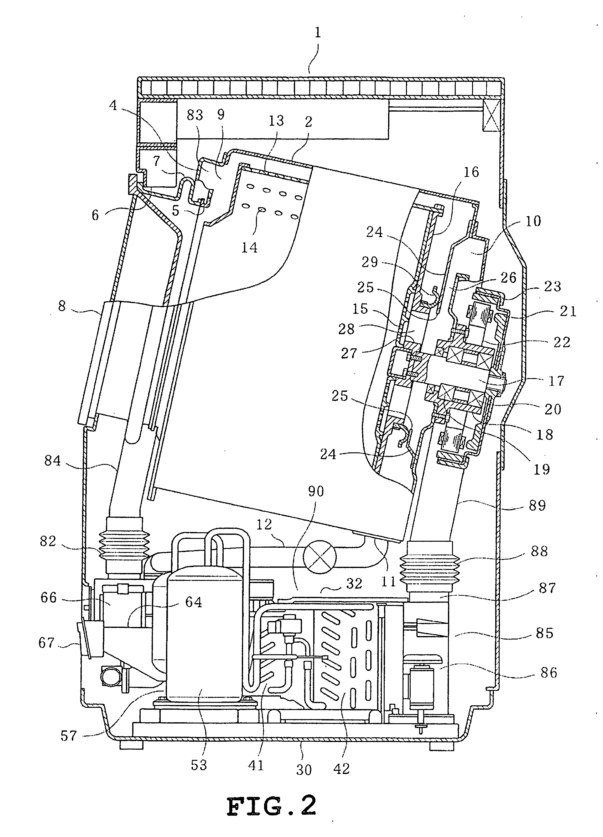
[0022]A detailed description will be given on the present invention with reference to the accompanying drawings.

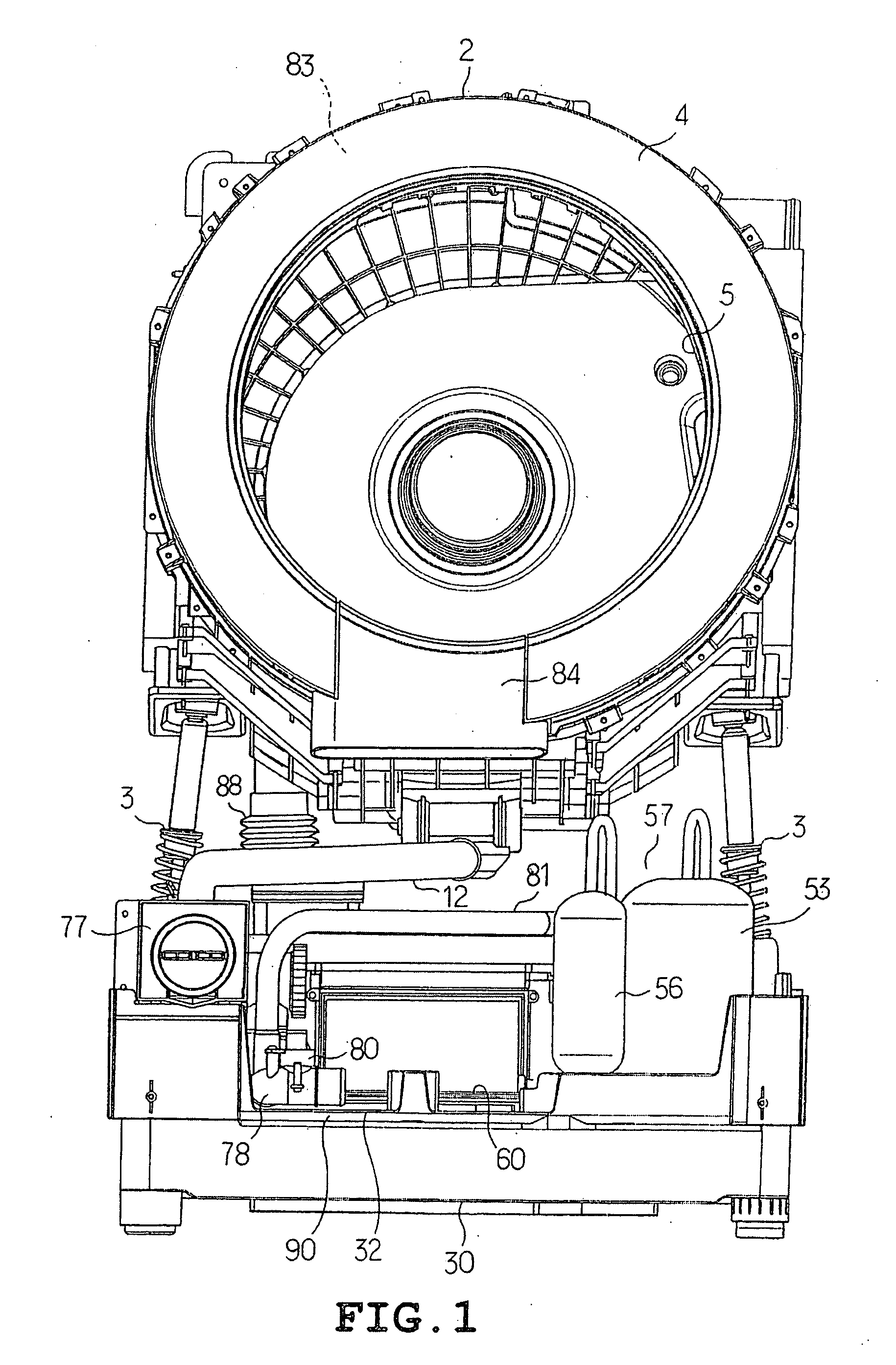
[0023]FIGS. 1 to 10 illustrate one exemplary embodiment of the present invention.

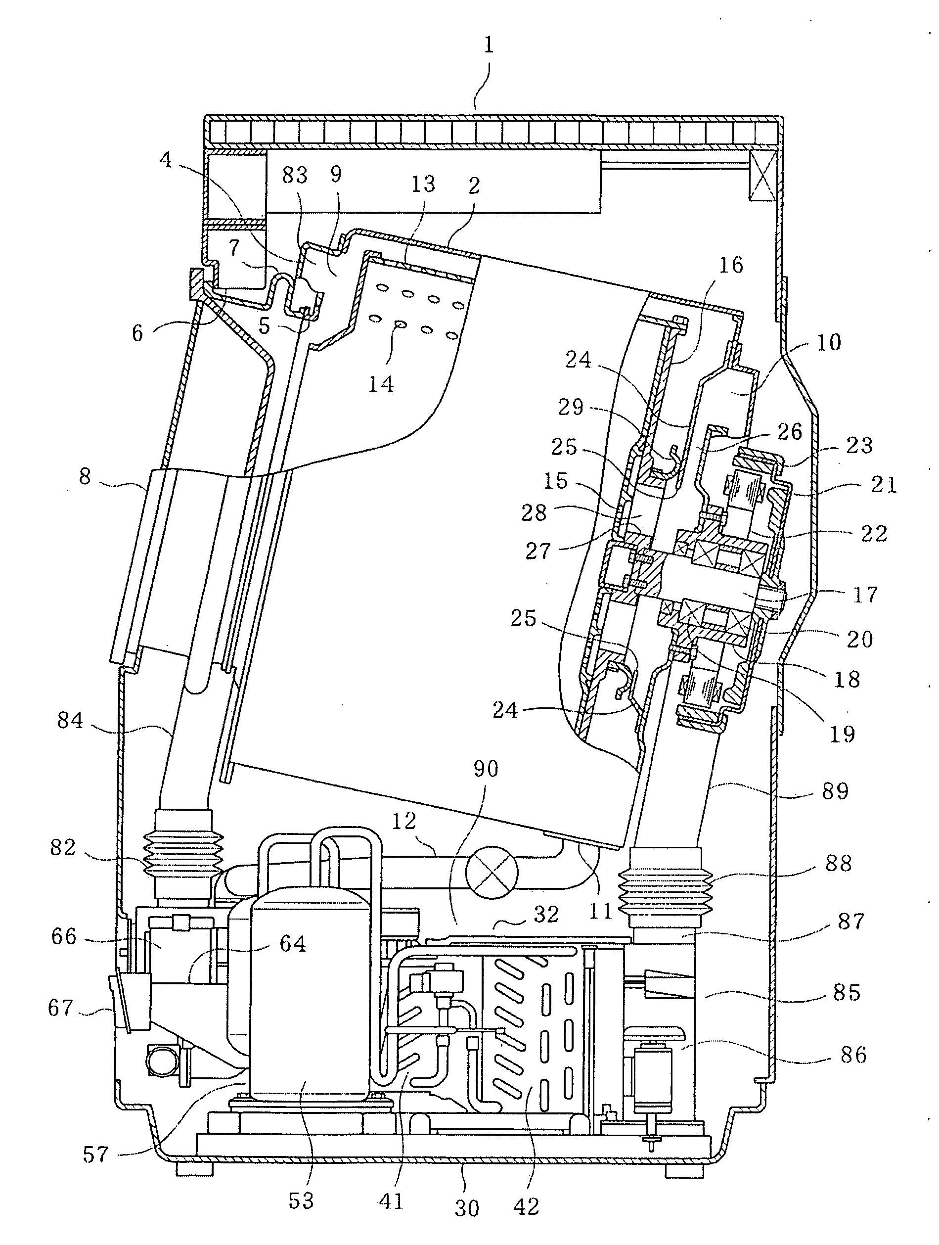
[0024]FIG. 2 illustrates the overall configuration of the drum-type washer / dryer. A cylindrical water tub 2 is supported by a pair of left and right suspensions 3 (refer to FIG. 1) inside a cabinet 1 constituting the exterior housing of the drum-type washer / dryer. The water tub 2 is laterally disposed with its axis running in the longitudinal direction (left and right direction in FIG. 2) and being slightly inclined upward (inclined leftwardly upward in FIG. 2). Also, an annular water tub cover 4 having an opening 5 in its substantial center is mounted on the front end of the water tub 2. An opening 6 is provided on the front surface of the cabinet 1 for loading and unloading of laundry. The opening 5 of the water tub cover 4 communicates with the opening 6 by bellows 7. An openable / closable d...


PUM


Abstract

A warm air inlet (10) and a warm air outlet (9) of a laterally provided cylindrical water tub (2) are separately arranged in the direction of the axis of the water tub (2). An airflow duct (32) connecting the warm air inlet (10) and the warm air outlet (9) is placed in the axis direction of the water tub (2), substantially directly below the water tub (2). A compressor (53) of a heat pump (57) having an evaporator (41) and a condenser (42) that are placed in the airflow duct (32) is placed at a position at a side of the airflow duct (32) so as to be orthogonal to the axis direction of the tub (2).

Description

TECHNICAL FIELD[0001]The present invention relates to a drum-type washer / dryer provided with a heat pump for drying laundry.BACKGROUND ART[0002]A washer / dryer provided with a heat pump for drying laundry is notable for its high dry capability and effective energy saving. In such a washer / dryer, the evaporator condenses and collects vapor emitted from laundry during the laundry dry operation. The compressor compresses the refrigerant, which has collected latent heat during vapor condensation, to elevate the temperature of the refrigerant. The condenser heats the air used in the dry operation with the refrigerant of elevated temperature. The use of latent heat obtained during vapor condensation as source of energy for heating the air used in the dry operation does indeed cause slight exterior heat loss (energy loss); however, most of the energy can be reused without loss. Therefore, efficient dry operation can be realized.[0003]The drum-type washer / dryer having a heat pump is provided...

Claims


Application Information

Patent Timeline
Patent Type & Authority Applications(United States)
IPC IPC(8): D06F29/00
CPCD06F25/00D06F58/206D06F58/24D06F39/04D06F58/02D06F2103/54D06F2103/56
Inventor HISANO, KOJIFUNAKI, KAZUO
Owner TOSHIBA HA PROD
Why Eureka
Try Eureka