Retractable multiposition furniture system

a multi-position, furniture technology, applied in the field of special purpose furniture, can solve the problems of a single user who must visualize a display while simultaneously entering data or controls reflected in the display, and the use of conventional equipment by a single user can be difficult, and the problem of exacerbated problems

Inactive Publication Date: 2007-02-20
GOZA SHIRLEY C
View PDF23 Cites 86 Cited by
  • Summary
  • Abstract
  • Description
  • Claims
  • Application Information

AI Technical Summary

Benefits of technology

[0011]The top and bottom of the presentation support structure includes panels that extend away at right angles to cooperate with sidewalls that extend away at right angles from the work support structure to form an enclosed storage cabinet when the work support structure is retracted into position against the presentation support structure. In applications that require temporary or intermittent use of the workstation while the workstation has been adjusted to a specific position or orientation relative to an immobile user, for example, a bedridden patient, the working area of the workstation can be closed up against the presentation area of the workstation to minimize the space occupied by the workstation when it is not being used. In these applications, the workstation is left in its extended position with the work support structure retracted, forming an attractive closed cabinet occupying a minimum of space. When the workstation is again needed, it can be easily accessed by the unassisted user.
[0014]The work support structure of the workstation has a working side and an ornamental side. By suitably adjusting the work support structure relative to the presentation support structure, the ornamental side replaces, or overlays, the presentation support structure from the perspective of the user of the furniture. Placing the work support structure against the presentation support structure also minimizes the external dimensions of the furniture system, making it more compact, when the system is not being used. The sides on the work support structure and the top and bottom top panels on the presentation support structure, in addition to completing a cabinet-like enclosure for the retracted workstation, are provided with ornamental exterior surfaces that coordinate with the visible surfaces of the retracted workstation.
[0019]From the foregoing, it may be appreciated that a primary object of the present invention is to provide an attractive furniture system that can be adjusted to meet the requirements of a wide range of users.
[0020]Another object of the present invention is to provide a furniture system that allows presentation material and working areas of the furniture to be adjusted as required to meet the requirements of a standing, sitting or reclining user.
[0021]It is also an object of the present invention to provide a system of furniture in which an assembly of a working support structure and a presentation support structure are combined with a mounting structure such that each of the structures is adjustable relative to the other to provide optimal user facility and to be retractable and nestable to a compact storage condition.
[0023]An object of the present invention is to provide a compact, adjustable furniture system mounted on a cabinet pedestal for providing an adjustable assembly of a work surface and a presentation area wherein the work surface can be folded up to the presentation area to form a cabinet-like enclosure and the assembly can be positioned directly over the cabinet pedestal for storage.

Problems solved by technology

However, conventional wall mounted workstations cannot be conveniently mounted on the wall between such beds because of the usual presence on the wall of equipment used to administer oxygen and monitor the patients' vital signs.
The use of such conventional equipment by a single user who must visualize a display while simultaneously entering data or controls reflected in the display can be difficult.
The problem can be exacerbated when the same unit of equipment is to be used by different individuals, in different environments and with different physical requirements.

Method used


Image

  • Retractable multiposition furniture system
  • Retractable multiposition furniture system
  • Retractable multiposition furniture system

Examples


Embodiment Construction

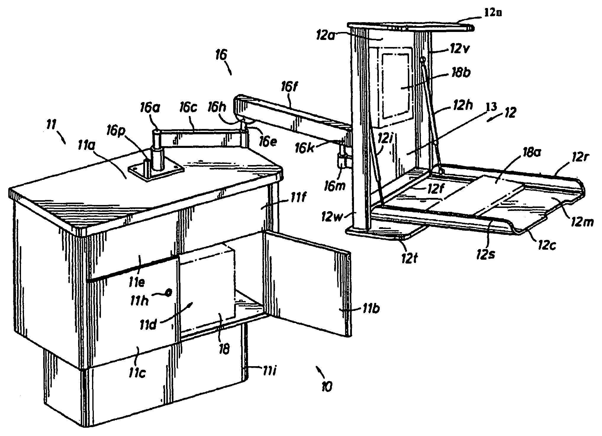
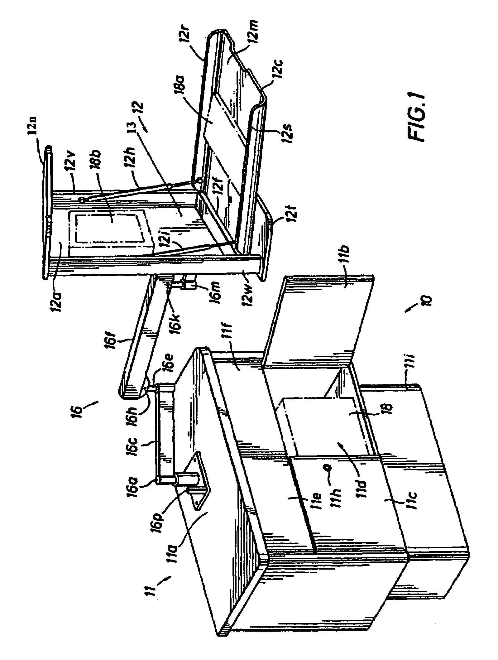
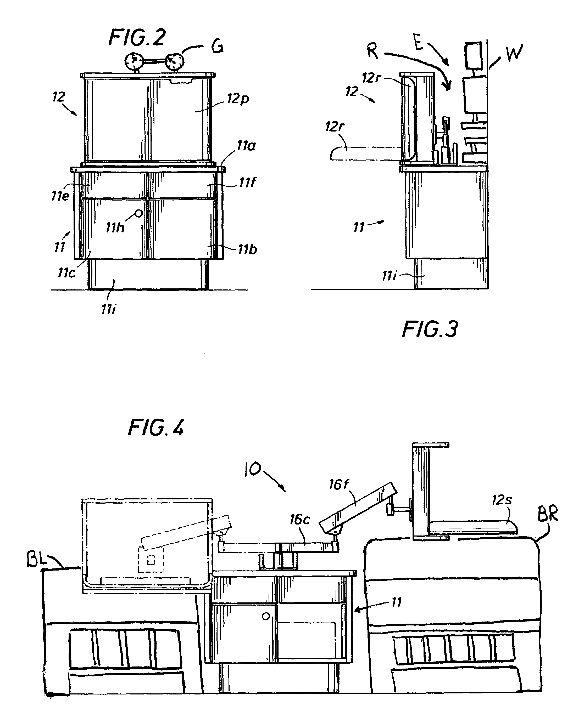
[0036]The furniture system of the present invention is indicated generally at 10 in FIG. 1. The system 10 includes a cabinet pedestal mount indicated generally at 11 and a workstation comprising a visual and work area presentation assembly indicated generally at 12. The workstation 12 is adjustably mounted on the cabinet pedestal 11 by a counterbalanced arm assembly indicated generally at 16. The arm assembly 16 is bolted or otherwise suitably secured to a top 11a of the cabinet pedestal 11. The external surfaces of the furniture system 10 are preferably provided with a decorative coating or layer of decorative material to achieve a desired furniture appearance.

[0037]The arm assembly 16 may be any suitable assembly that provides the desired degree of flexibility and adjustability for the workstation 12. The arm 16 is constructed of metal, with pivoting mounts, spring biasing elements and clamping components that provide the desired range of adjustable movements. Such arm assemblies ...


PUM


Abstract

A workstation providing multiple presentation angles for a visible display structure and a related working area structure. The display and working structures are adjustably mounted on a cabinet pedestal that houses electronic equipment connected with components carried by the display and working area structure. The cabinet pedestal is positioned against a wall below gauges and / or other materials mounted on the wall. When not being used, the working area structure closes over the visible display structure to provide a decorative cover over an enclosed area. The display and work structures are retractable to a compact standby position at the top of the cabinet, leaving certain of the wall-mounted materials visible over the top of the stored workstation. A recess provided between the back of the stored display and work structure accommodates certain wall mounted materials.

Description

CROSS-REFERENCE TO RELATED APPLICATIONS[0001]This application claims the benefit of U.S. Provisional Application Ser. No. 60 / 446,722 filed Feb. 10, 2003.BACKGROUND OF THE INVENTION[0002]1. Field of the Invention[0003]The present invention relates to special purpose furniture that can be adjusted to accommodate differently situated users.[0004]2. Description of Related Prior Art[0005]Wall mounted workstations that can be opened for use and subsequently folded back up when not in use have commonly been employed for providing a retractable visual presentation area and work surface. Such workstations sometimes contain a computer monitor in the visual presentation area and a keyboard on the work surface. When not in use, the workstation is retracted by being folded together to assume a compact, closed cabinet-like container against the wall upon which it is mounted. These workstations are particularly useful in medical facilities where doctors and technicians can conveniently access a co...

Claims


Application Information

Patent Timeline
Patent Type & Authority Patents(United States)
IPC IPC(8): A47B37/00A47B21/03
CPCA47B21/0314A47B2021/0321
Inventor GOZA, ROGER
Owner GOZA SHIRLEY C
Why Eureka
Try Eureka