
Flow meter

a flowmeter and flow rate technology, applied in the direction of dynamic fluid flow effect, volume/mass flow, instruments, etc., can solve the problems of high cost of retrofitting of flowmeters, high cost of conventional ultrasonic flowmeters, and difficult to obtain flow measurement in existing pipework

Inactive Publication Date: 2011-08-04
VELCON FILTERS
View PDF9 Cites 0 Cited by
  • Summary
  • Abstract
  • Description
  • Claims
  • Application Information

AI Technical Summary

Benefits of technology

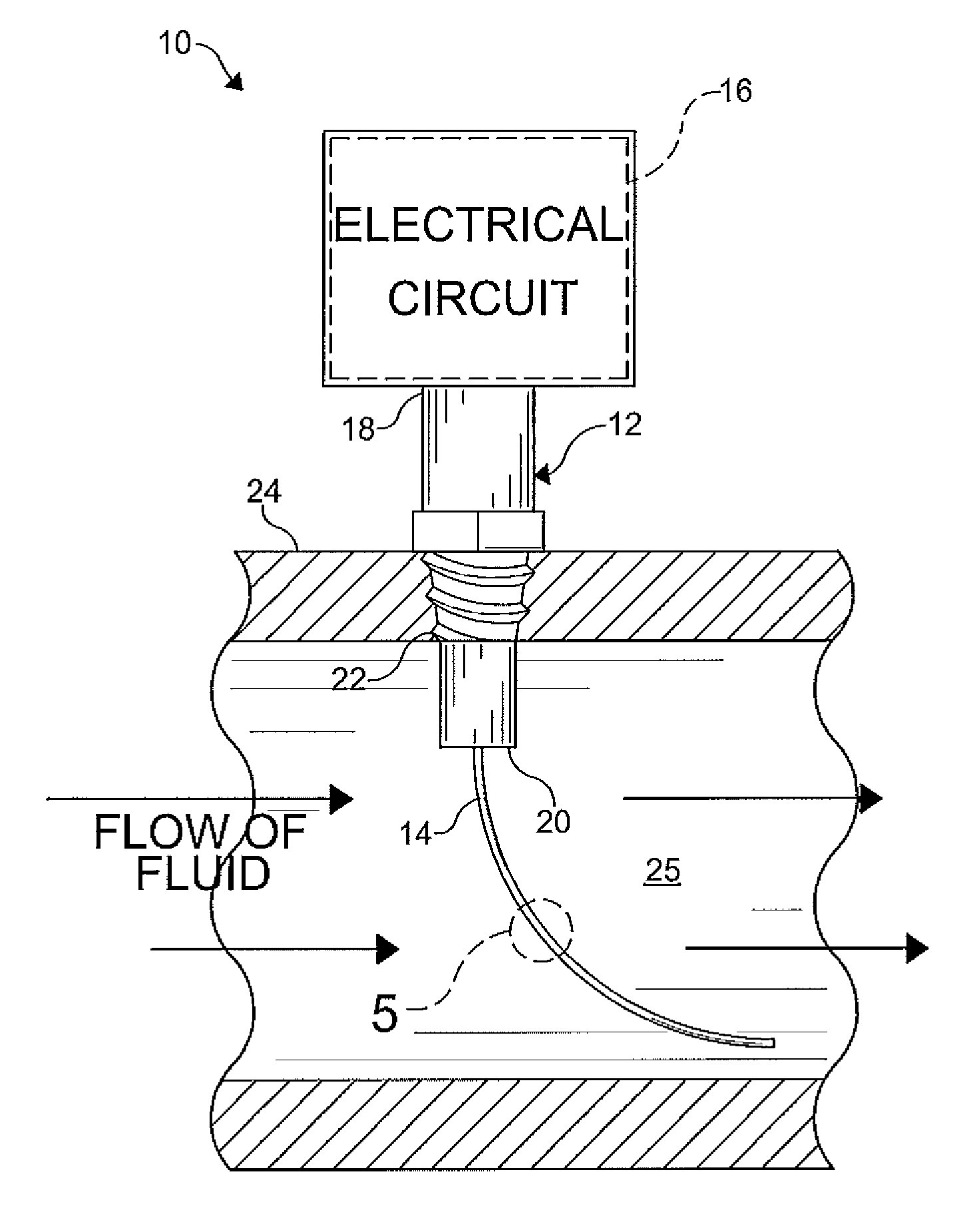
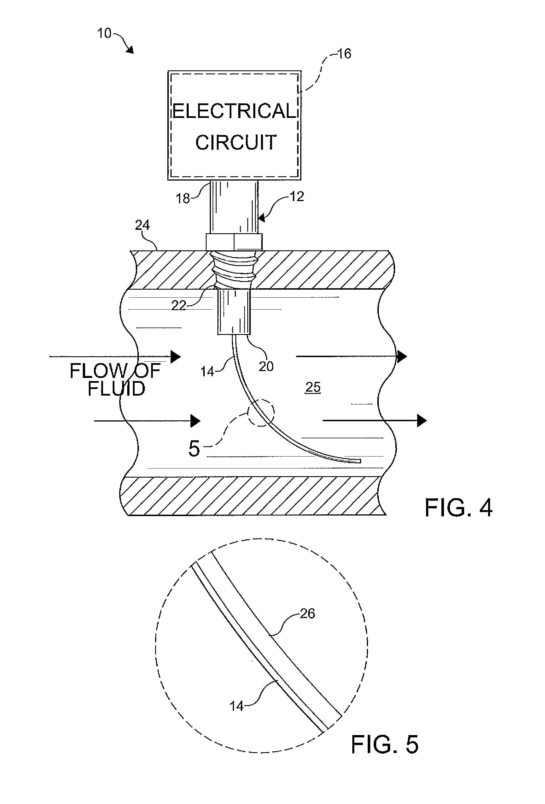
[0011]One method comprises the steps of: coupling a flow meter to a pipe, the flow meter including: a main body having a first end and a second end, the second end disposed in an interior of the pipe; and a flexible electrical resistor coupled to the main body and extending outwardly from the second end thereof, wherein an electrical resistance of the flexible electrical resistor is varied in response to a flexure thereof; passing a fluid through the pipe, the fluid causing the flexible electrical resistor to flex from a resting configuration; and sensing the flexure of the flexible electrical resistor.

Problems solved by technology

Accordingly, flow measurement can be very difficult to obtain in existing pipework.
Retrofitting of flowmeters is usually expensive.
However, conventional ultrasonic flowmeters are expensive.

Method used


Image

  • Flow meter
  • Flow meter
  • Flow meter

Examples


Embodiment Construction

[0018]The following detailed description and appended drawings describe and illustrate various embodiments of the invention. The description and drawings serve to enable one skilled in the art to make and use the invention, and are not intended to limit the scope of the invention in any manner. In respect of the methods disclosed, the steps presented are exemplary in nature, and thus, the order of the steps is not necessary or critical.

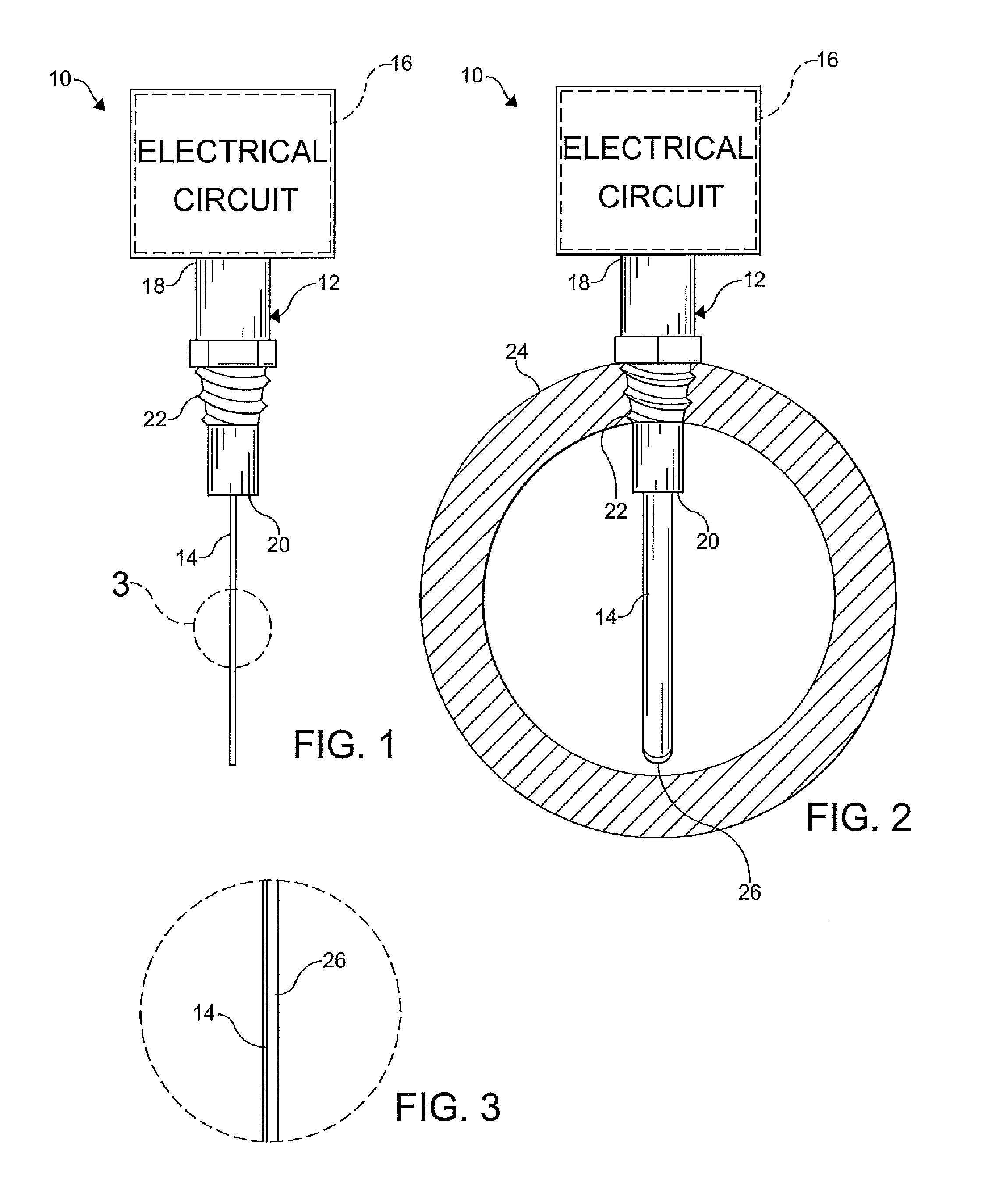
[0019]FIGS. 1-5 illustrate a flow meter 10 according to an embodiment of the present invention. As shown, the flow meter 10 includes a main body 12 (i.e. housing), a flexible electrical resistor 14, and an electrical circuit 16 in electrical communication with the flexible electrical resistor 14. It is understood that the flow meter 10 can include additional components. The flow meter 10 is typically disposed within a fluid processing system (not shown). It is understood that the flow meter 10 can be coupled to or integrated with any system or fluid c...


PUM


Abstract

A flow meter includes a main body having a first end and a second end, a flexible electrical resistor coupled to the main body and extending outwardly from the second end thereof, wherein an electrical resistance of the flexible electrical resistor varies in response to a flexure thereof, and an electrical circuit in electrical communication with the electrical resistor to detect a flexure of the electrical resistor.

Description

CROSS REFERENCE TO RELATED APPLICATIONS[0001]This application is entitled to the benefit of, and claims priority to, U.S. provisional patent application Ser. No. 61 / 301,445 filed Feb. 4, 2010, the entire disclosure of which is incorporated herein by reference.FIELD OF THE INVENTION[0002]The present invention relates to flow meters and more particularly to a meter for use in connection with the measurement of fluid flow in a piping system.DESCRIPTION OF THE PRIOR ART[0003]Flow measurement in pipes is essential to many fluid processes. In many cases, flow measurement is needed after a piping system has been completed, and no flowmeter has been installed into the original pipework. Accordingly, flow measurement can be very difficult to obtain in existing pipework. Retrofitting of flowmeters is usually expensive. Typically, an ultrasonic flowmeter, which can measure the flow through the pipe walls, is secured to an exterior of the pipework. However, conventional ultrasonic flowmeters ar...

Claims


Application Information

Patent Timeline
Patent Type & Authority Applications(United States)
IPC IPC(8): G01R27/08
CPCG01R27/08G01F1/28
Inventor STEVENS, JED BABBINGTONSPRENGER, GREGORY SCOTTGISH, MICHAEL J.
Owner VELCON FILTERS
Learn More