One cycle control PFC boost converter integrated circuit with inrush current limiting, fan motor speed control and housekeeping power supply controller

a technology of inrush current limitation and boost converter, which is applied in the direction of electric variable regulation, process and machine control, instruments, etc., can solve the problems of high discrete component count, complicated design and development effort required to implement high-performance continuous conduction mode power factor correction converter, and more difficult to implement a single-package design, so as to eliminate noise coupling and improve overall performance

Active Publication Date: 2006-06-27
INFINEON TECH AMERICAS CORP
View PDF9 Cites 94 Cited by
  • Summary
  • Abstract
  • Description
  • Claims
  • Application Information

AI Technical Summary

Benefits of technology

[0015]A second peripheral feature included in the PFC IC is a fan speed controller. A fan is often used to provide power supply cooling. Often this feature has to be implemented with external circuitry dedicated to fan speed control. This feature can be included onboard the PFC controller given that the load conditions of the power supply are all available internal to the PFC controller. The controller also has an on-board oscillator, which can be used for the Fan speed control PWM signal eliminating redundant switching circuits.
[0016]The fan speed can be directly controlled as a function of the PFC load current thus eliminating the need for complicated control schemes.
[0022]3. Synchronization of switching frequencies eliminates noise coupling and improves overall performance.
[0023]4. Use of the VCC pin as the feedback pin for the housekeeping control section eliminates a redundant feedback pin.
[0024]Inclusion of this function onboard the PFC controller is simplified given that the controller already has an oscillator and the VCC pin can be used as the feedback pin for the housekeeping section eliminating extra pins.

Problems solved by technology

The above prior art using the multiplier approach has the disadvantage of high discrete component count and complicated design and development effort required to implement high performance continuous conduction mode power factor correction converters.
In addition, it is more difficult to implement a “single package” design wherein the switch is packaged with the control circuit because of the high component count and numbered pins.

Method used


Image

  • One cycle control PFC boost converter integrated circuit with inrush current limiting, fan motor speed control and housekeeping power supply controller
  • One cycle control PFC boost converter integrated circuit with inrush current limiting, fan motor speed control and housekeeping power supply controller
  • One cycle control PFC boost converter integrated circuit with inrush current limiting, fan motor speed control and housekeeping power supply controller

Examples


Embodiment Construction

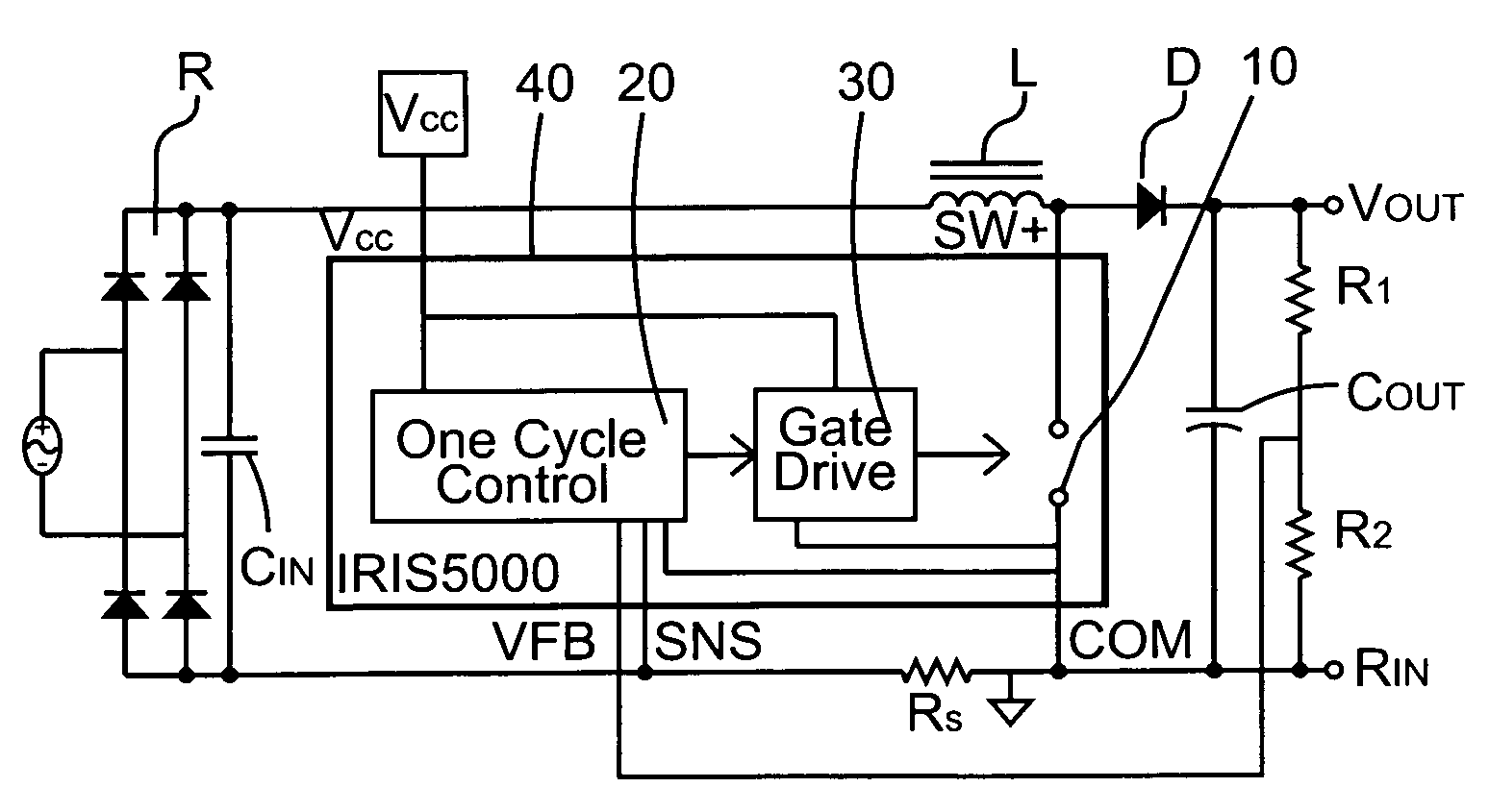
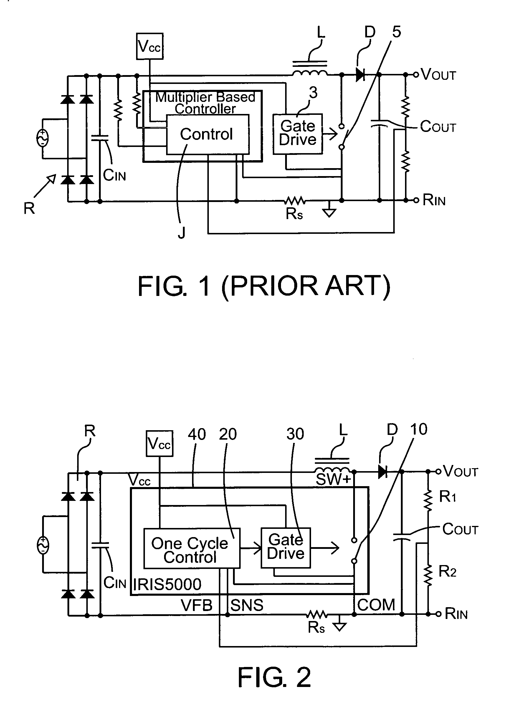
[0041]FIG. 2 depicts a system level block diagram representation based on the OCC active power factor correction technique operating in a fixed frequency, continuous conduction mode boost converter topology. In CCM, the current in the inductor L is never allowed to become zero. In the circuit of FIG. 2, the power switch 10 and the OCC based PFC control circuit 20 with on board power switch driver 30 are integrated into a single package 40 capable of dissipating appropriate heat from the device to a heat sink. Various power packages can be employed using this technique since the number of pins required to implement a full CCM PFC boost converter is reduced with the use of the OCC technique.

[0042]The control circuit 20 is based on the OCC method in which the multiplier and input voltage sensing referred to in the prior art circuit of FIG. 1 are not required. This allows package pins and external components of the IC 40 to be reduced. The OCC concept is realized with a simple linear ci...


PUM


Abstract

A power factor corrected boost converter circuit includes a rectifier connectable to an ac input and having a rectified dc output provided across a dc bus, an inductor having first and second terminals connected in one leg of the dc bus, an integrated circuit comprising a control circuit for controlling a switch, the integrated circuit including a housing enclosing the control circuit, the integrated circuit having a power terminal, a ground terminal, a first control input terminal coupled to an output of the converter circuit, and a second control input terminal coupled to a sensor for sensing current in the dc bus and further having an output terminal connected to the switch, a boost rectifier diode having a first terminal, the diode coupled to the inductor, and a storage capacitor connected to the diode. The control circuit comprises a one cycle control circuit having an integrator reset by a clock signal for each cycle of the clock signal. The circuit further includes any or all of an inrush current limiting circuit for limiting the current through the inductor to a value below a predetermined level, a fan motor speed controller and a housekeeping power supply controller.

Description

CROSS REFERENCE TO RELATED APPLICATION[0001]This application is based on and claims priority to U.S. Provisional Application Ser. Nos. 60 / 423,191, filed Nov. 1, 2002 by Frank Athari entitled “ONE CYCLE CONTROL CONTINUOUS CONDUCTION MODE PFC BOOST CONVERTER IC WITH INRUSH CURRENT LIMIT AND FAN SPEED CONTROL” and Ser. No. 60 / 431,858, filed Dec. 9, 2002 by Frank Athari entitled “CONTINUOUS CONDUCTION MODE PFC BOOST CONVERTER IC WITH INTEGRATED INRUSH CURRENT LIMITED, FAN SPEED AND HOUSEKEEPING CONTROL”, the entire disclosures of which are incorporated by reference herein.BACKGROUND OF THE INVENTION[0002]The One Cycle Control (OCC) technique for controlling switching circuits is now known. The general technique is described in U.S. Pat. No. 5,278,490. The technique is applied to a PFC (Power Factor Correction) boost converter in U.S. Pat. No. 5,886,586. In the OCC technique, as applied to a PFC boost converter circuit, the output voltage of the converter is sensed, compared to a referen...

Claims


Application Information

Patent Timeline
Patent Type & Authority Patents(United States)
IPC IPC(8): G05F1/10H02M1/00H02M1/42
CPCH02M1/4225Y02B70/126Y02B70/10H02M3/28
Inventor ATHARI, FRANK
Owner INFINEON TECH AMERICAS CORP
Why Eureka
Try Eureka