Variable speed hydraulic pump

a hydraulic pump and variable speed technology, applied in the field of hydraulic pumps, can solve the problems of high heat generation, high cost of the pump, and inability to meet the needs of many applications, and achieve the effects of low presssure, high flow rate, and high flow ra

Inactive Publication Date: 2005-03-08
ENERPAC TOOL GRP CORP
View PDF15 Cites 95 Cited by
  • Summary
  • Abstract
  • Description
  • Claims
  • Application Information

AI Technical Summary

Benefits of technology

In practicing the invention, since the pump is controlled by an electronic controller, the prior art pump's first stage bypass valve can be eliminated. Elimination of this bypass valve produces additional benefits since heat generated by the valve and the resulting-destruction of hydraulic oil is eliminated.
The invention also results in higher flow rates, at a given maximum horsepower rating, particularly for pressures that are above the first stage maximum pressure and below the second stage maximum pressure. The prior art pump has a flow curve that drops off at 1000 psi and remains constant until maximum pressure. This means that the flow at 3000 psi is the same as the flow at 10,000 psi. The new pump maximizes the flow at each pressure. For example, the flow at 3000 psi would be over 3 times greater than the flow at 10,000 psi.
It is preferred to use a gear pump in series to pre-charge a piston pump which is driven to supply the load. The gear pump provides a relatively low presssure (up to 100 psi for example) to provide a flow to the main pump with a pressure and flow rate that varies proportionally with pump speed so as to precharge the main pump and inhibit or prevent cavitation. At high speed the pressure is higher to help fill the main pump in less time. At low speeds, the pressure is lower, but cavitation is not a problem at low speeds.
Another preferred aspect of the invention is positive return of the piston or pistons of the main pump. In the prior art, the pistons were driven in reciprocation by a cam eccentric journalled to the drive shaft of the pump, and each piston...

Problems solved by technology

This dumping also creates a large amount of heat because the heat generated is a function of the flow and pressure.
Requiring a pressure detector adds expense to the pump, making it impractical for many applications.
These pumps are generally limited to lowe...

Method used


Image

  • Variable speed hydraulic pump
  • Variable speed hydraulic pump
  • Variable speed hydraulic pump

Examples


Embodiment Construction

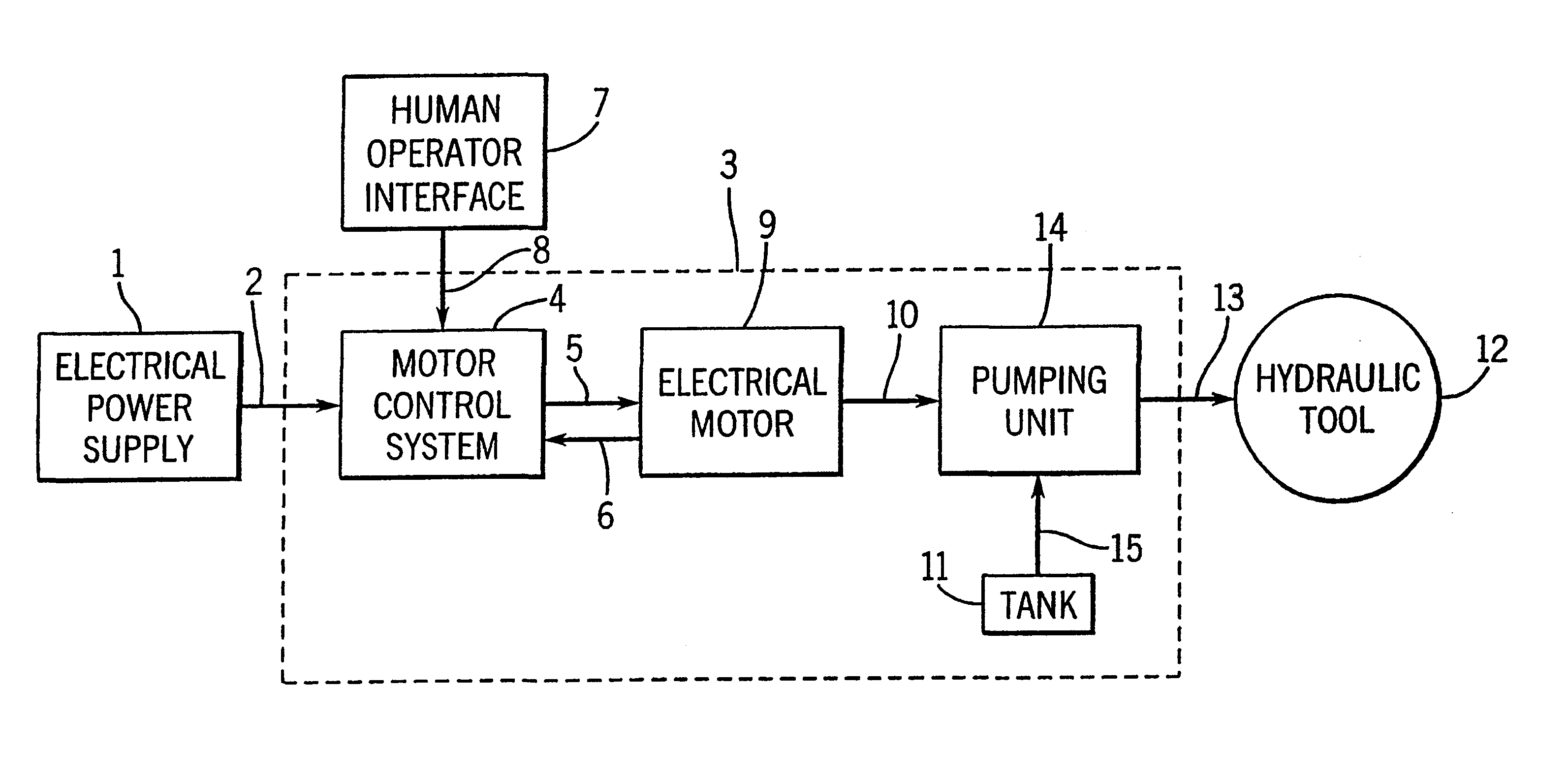
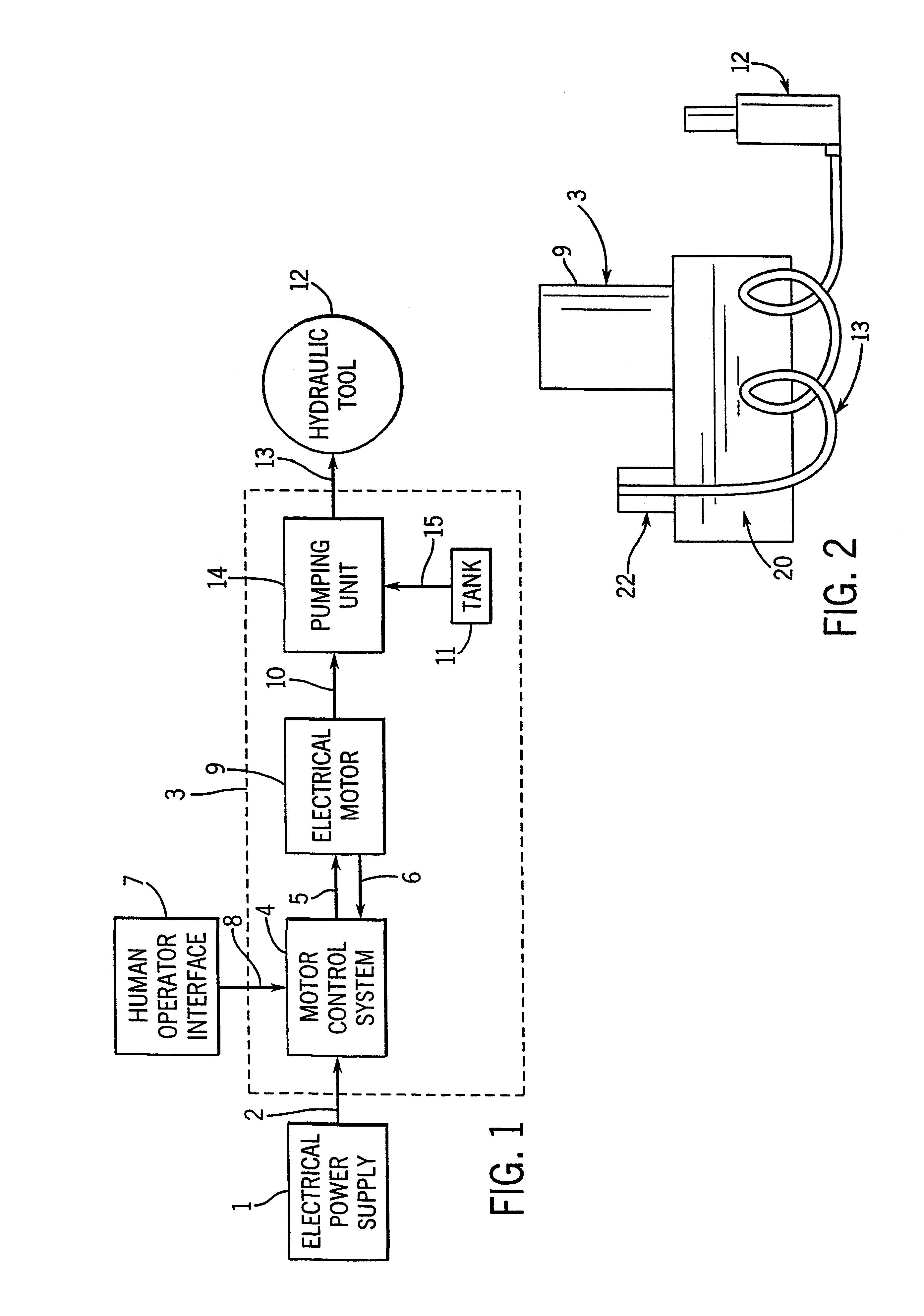
Referring to FIG. 1, there is illustrated a block diagram of the variable speed pump. The block labeled 3 corresponds to the variable speed pump invention. The electrical power supply 1 to the pump is obtained through standard electrical distribution such as 120 VAC, 240 VAC, or other voltages and may be single phase or three phase in nature. It is shown supplying the pump 3 with electrical power by means of line 2. The output of the pump is a hydraulic line 13 that feeds a hydraulic tool 12, for example. The pump also has provisions for a human operator interface, i.e., a remote control pad, as shown by block 7. Block 7 provides inputs to the pump 3 such as power on, power off, forward, reverse and so on. These functions are communicated to the pump by means of line 8.

The variable speed pump 3 has three main components indicated by the motor control system 4, the electrical motor 9 and the hydraulic pumping unit 14. The pump also has a tank 11 to supply hydraulic fluid to the pump ...


PUM


Abstract

The invention provides a variable speed hydraulic pump designed to operate at a maximum horsepower throughout its pressure range by adjusting motor speed according to motor load parameters. In particular, the variable speed hydraulic pump includes a hydraulic pump unit coupled to a variable speed electric motor by a drive unit and to a hydraulic fluid tank for pressurizing and pumping hydraulic fluid when operated by the motor. A motor controller is electrically connected to the motor to supply drive signals to the motor based on electrical characteristics of the drive signals which are dependent on the load exerted on the motor. Suction from the load is provided by both the main pump and a bidirectional supercharging pump by reversing the direction of the motor and shifting a 4/3 valve to connect the main pump inlet to the load and its outlet to tank. In addition, the controller reduces the motor speed at the maximum rated pressure to just maintain the pressure, to reduce the amount of fluid pumped through the maximum pressure relief valve.

Description

STATEMENT OF GOVERNMENT SPONSORED RESEARCH / DEVELOPMENTNot applicable.BACKGROUND OF THE INVENTION1. Field of the InventionThis invention relates to hydraulic pumps, and in particular to a variable speed hydraulic pump.2. Discussion of the Prior ArtHydraulic pumps are useful for providing power to a work producing device by means of hydraulic fluid under pressure. Hydraulic pumps are used to supply hydraulic fluid pressure for lifting, pressing, punching, and other mechanical operations when used with suitable hydraulic presses, punches, cylinders, and other devices.Pumps which provide the fluid for these applications typically have a nonlinear flow versus pressure characteristic curve. At low pressures, the flow is high and as the pressure increases, at a certain pressure the flow is drastically reduced. Having a high flow at low pressures greatly reduces cycle times for improved productivity and produces high performance for industrial applications, and the ability to produce high p...

Claims


Application Information

Patent Timeline
IPC IPC(8): F04B49/20F04B1/04F04B23/10F04B23/00F04B1/00
CPCF04B1/0426F04B23/103F04B49/20F04B2203/0209F04B2203/0201F04B2203/0207F04B2203/0208F04B2201/1203
Inventor BISHOP, MICHAEL B.PILI, ROGER R.KNUTH, BRUCE E.BARANI, MOE K.FLANARY, RONMENTINK, LAURENTIUS A. G.STEBER, GEORGE R.PIEDL, MARTIN
Owner ENERPAC TOOL GRP CORP
Why Eureka
Try Eureka