System and method of conditioning respiratory gases

A breathing gas and regulating system technology, applied in the direction of respirators, etc., can solve the problem of unreliable fine adjustment of humidity level

Inactive Publication Date: 2009-04-22
柯惠股份公司
View PDF1 Cites 6 Cited by
  • Summary
  • Abstract
  • Description
  • Claims
  • Application Information

AI Technical Summary

Problems solved by technology

[0037] Several of the systems described in WO2006/127257, although successful, have proven to be ineffect...

Method used


Image

  • System and method of conditioning respiratory gases

Examples


Embodiment Construction

[0041] A non-limiting embodiment of the invention is illustrated by way of example with reference to the accompanying drawings.

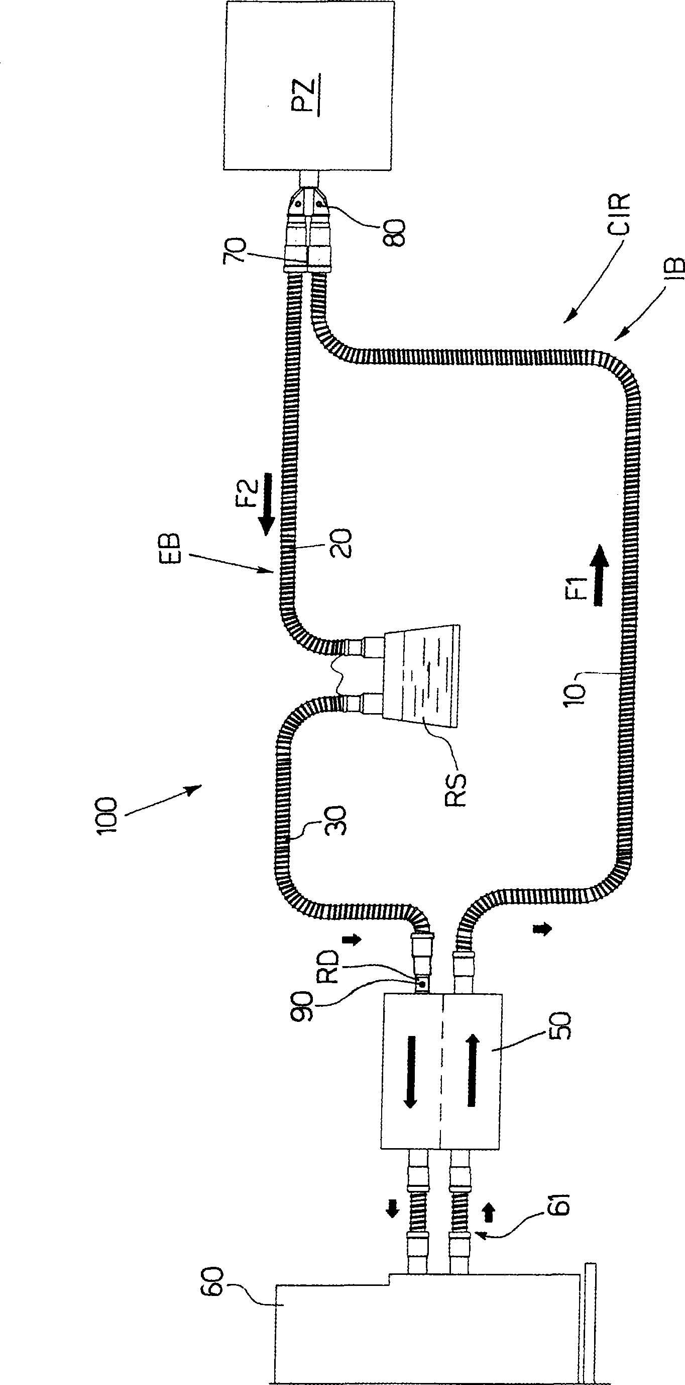
[0042] As shown in the accompanying drawings, the system (100) according to the present invention comprises:

[0043] - three temperature-regulated conduits 10, 20, 30, one for the inspiratory branch IB and the other two for the expiratory branch EB;

[0044] - a reservoir RS containing water, possibly heated by a resistor (not shown), and which has a filling opening, characterized by a small amount of water, positioned along the exhalation branch EB;

[0045] - a heat and moisture exchanger (HME) 50, characterized by a strict separation of the inspiratory flow F1 and the expiratory flow F2, which is located near the ventilator 60 and serves to separate the inspiratory and expiratory flows while still ensuring that both between the correct heat and humidity exchange, and does not increase the dead space in the circuit;

[0046] - a Y-shaped connec...


PUM


Abstract

A respiratory gas conditioning system (100) and a method are provided, including an inhale branch (IB), an exhale branch (EB), a low-dead-space heat and moisture exchanger (HME) (50), and a connector (70) for connecting the branches (IB, EB) to a patient (PZ,) characterized in that, the HME (50) is located close to a ventilator (60); and a water reservoir (RS) is located upstream from the HME (50) to moisture-enrich the gas exhaled by the patient (PZ) as it flows along the exhale branch (EB).

Description

technical field [0001] The present invention relates to a system and method for regulating breathing gases. [0002] The system and method are intended for use in intensive care to provide the correct humidity / temperature levels of gas to be inhaled by an intubated patient on artificial ventilation. [0003] The invention can be used particularly advantageously, but not exclusively, in anesthesiology and in the intensive care unit (ICU), to which the following description refers only by way of example. Background technique [0004] Currently, in the intensive care unit, the airway of an intubated patient on artificial ventilation is heated and humidified in two main ways, depending on how long the patient is expected to remain in intensive care. [0005] When the patient is expected to remain in intensive care for substantially less than 72 hours, a first passive conditioning system utilizing a heat and moisture exchanger (HME) is employed. [0006] It is well known that H...

Claims


Application Information

Patent Timeline
IPC IPC(8): A61M16/10
CPCA61M16/1075A61M2016/1095A61M16/16A61M16/1045A61M16/1095A61M16/0833
Inventor G·朱奇S·博拉里S·特拉里
Owner 柯惠股份公司
Why Eureka
Try Eureka