Medical heat and moisture exchanger (hme)

A technology of exchanger, humidity, applied in the direction of respirator, etc., can solve problems such as causing problems

Inactive Publication Date: 2008-11-26
柯惠股份公司
View PDF1 Cites 6 Cited by
  • Summary
  • Abstract
  • Description
  • Claims
  • Application Information

AI Technical Summary

Problems solved by technology

[0008] Additionally, in the case of pediatric or neonatal patients, the gas flow rates and volumes involved make the presence of a stagnant volume of ventilation gas a serious problem
[0009] Nevertheless, in prior art installations, the presence of even one HME usually causes problems

Method used


Image

  • Medical heat and moisture exchanger (hme)
  • Medical heat and moisture exchanger (hme)
  • Medical heat and moisture exchanger (hme)

Examples


Embodiment Construction

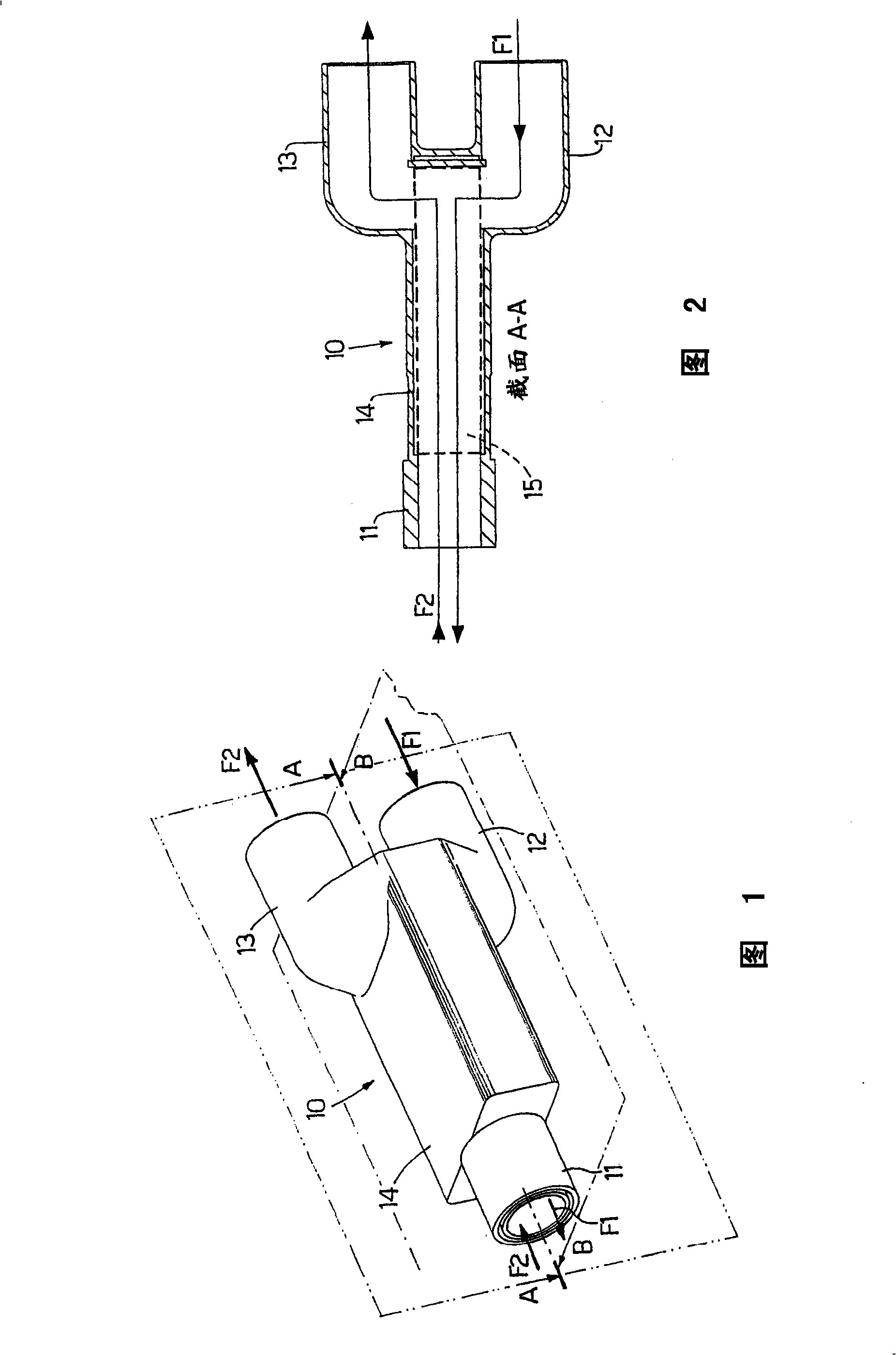
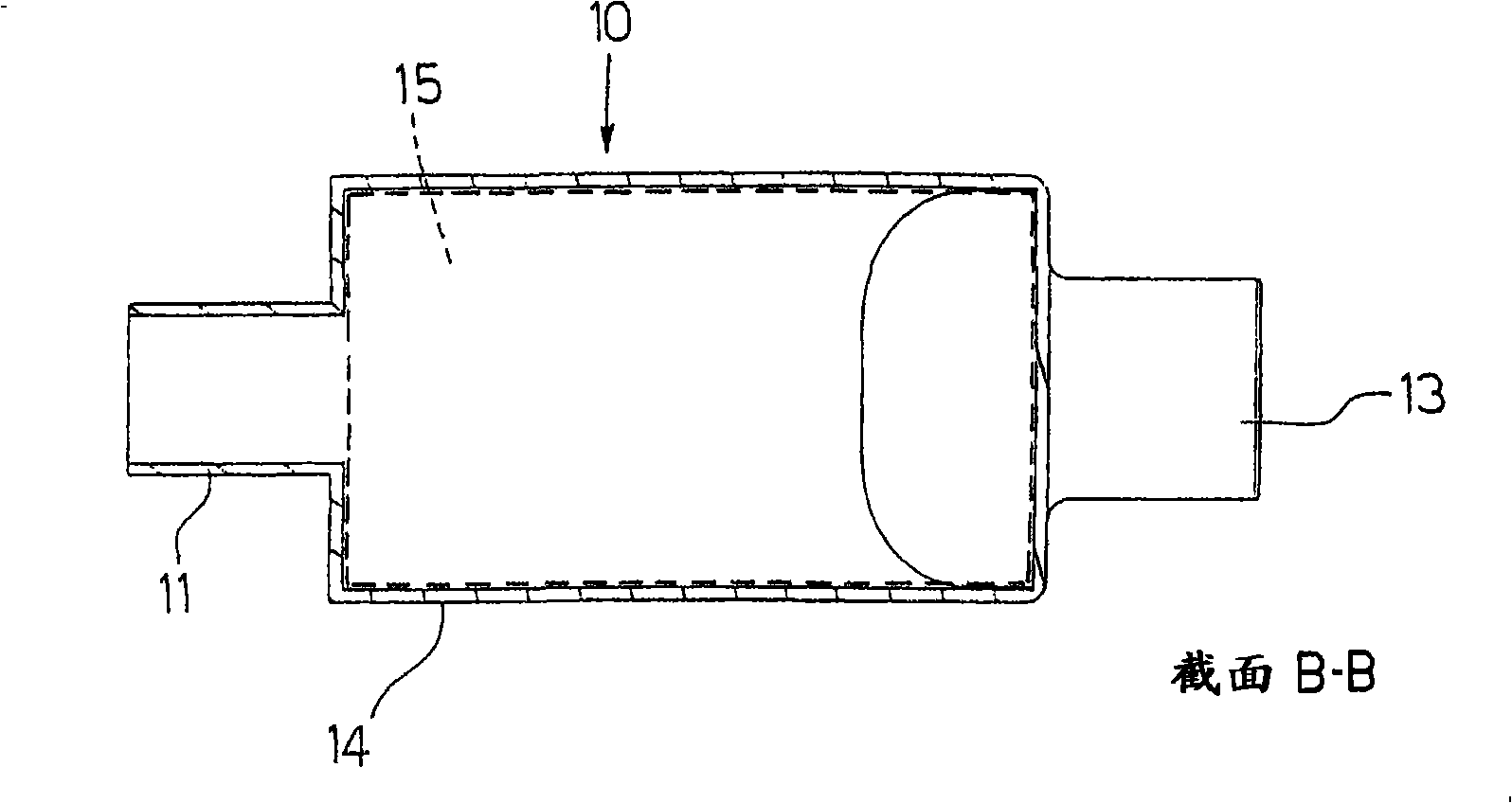
[0039] Figures 1, 2, 3, 4 show a first embodiment of an exchanger (HME) 10 according to the invention.

[0040] In the first embodiment, the exchanger 10 comprises a first substantially tubular connector 11 connected to an endotracheal tube (not shown) of a patient (not shown).

[0041] The exchanger 10 is also provided with a second substantially tubular connection 12, along which flows the inspiratory gas produced by a respirator (not shown) and indicated by the arrow F1.

[0042] The exchanger 10 also includes a third substantially tubular connection 13 along which the exhaled gas F2 is returned to the respirator.

[0043] Finally, the exchanger 10 comprises a substantially parallelepiped-shaped body 14 sandwiched between a first joint 11 on one side and joints 12, 13 on the other side.

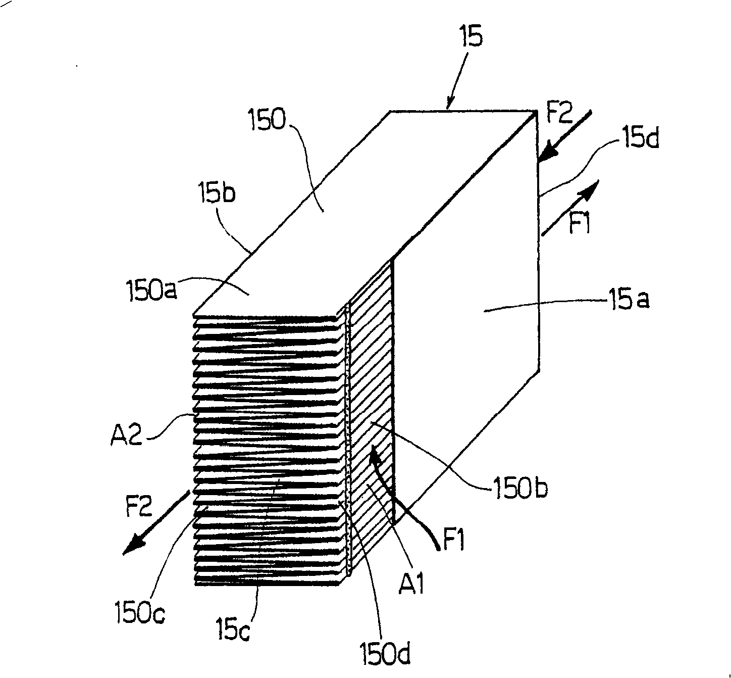
[0044] The body 14 houses a membrane (or filter) 15 through which heat and humidity are exchanged between the outgoing gas and the incoming gas. like Figure 4 As shown in detail in , t...


PUM


Abstract

An HME (heat and moisture exchanger) ( 10 ) having a septum (or filter) ( 15 ) formed by pleating a sheet ( 150 ) of material capable of retaining and releasing heat and moisture. The HME ( 10 ) is characterized in that walls ( 15 a, 15 b, 15 c) of the septum (or filter) ( 15 ) are coated partly or completely with sealing material to define at least two exposed areas (A 1, A 2 ) through which inhaled gas (F 1 ) and exhaled gas (F 2 ) flow respectively. Moreover, each sheet ( 150 ) of material is divided into identical units ( 150 a) ''fan-folded'', in use, one on top of another to form a first set of passages ( 150 b) through which only the inhaled gas (F 1 ) flows, and a second set of passages ( 150 c) through which only the exhaled gas (F 2 ) flows.

Description

technical field [0001] The present invention relates to a medical heat and humidity exchanger (HME). [0002] Rather, the invention can be advantageously, though not exclusively, used in anesthesia and intensive care, for which the following description is purely by way of example. Background technique [0003] As known, a heat and humidity exchanger (HME) is a device for anesthesia and intensive care of intubated patients with artificial respiration. [0004] In fact, in these cases the patient's upper airway is shunted and therefore unable to assist in heating and humidifying the cold, dry ventilation gas, between the so-called "catheter adapter" and the "patient-side Y-connector" in the breathing circuit An HME is inserted in between to retain the heat and humidity of the gas exhaled by the patient and heated and humidified by the lower airway, and to release most of the retained heat and humidity to the air supply inhaled by the patient. [0005] However, inserting an ...

Claims


Application Information

Patent Timeline
Patent Type & Authority Applications(China)
IPC IPC(8): A61M16/00
CPCA61M16/105A61M16/1045A61M16/08A61M16/0833A61M16/106
Inventor G·朱奇C·贝尔卢齐S·加林
Owner 柯惠股份公司
Why Eureka
Try Eureka