Method and apparatus for the detection of cracks in the teeth of generator rotors

A technology for generator rotors and rotor teeth, applied in measuring devices, using sound waves/ultrasonic waves/infrasonic waves to analyze solids, using sound waves/ultrasonic waves/infrasonic waves for material analysis, etc.

Inactive Publication Date: 2009-04-22
ALSTOM TECH LTD
View PDF1 Cites 10 Cited by
  • Summary
  • Abstract
  • Description
  • Claims
  • Application Information

AI Technical Summary

Problems solved by technology

[0007] However, the use of phased arrays requires very complex and sophisticated electronics to define and redirect the scanning beam and to extract useful data from the signals received by the phased array

Method used


Image

  • Method and apparatus for the detection of cracks in the teeth of generator rotors
  • Method and apparatus for the detection of cracks in the teeth of generator rotors
  • Method and apparatus for the detection of cracks in the teeth of generator rotors

Examples


Embodiment Construction

[0036] The present invention describes a novel ultrasound method which utilizes a simpler and more compact ultrasound pulse echo technique than the phased array method of the prior art (EP-A1-1777513).

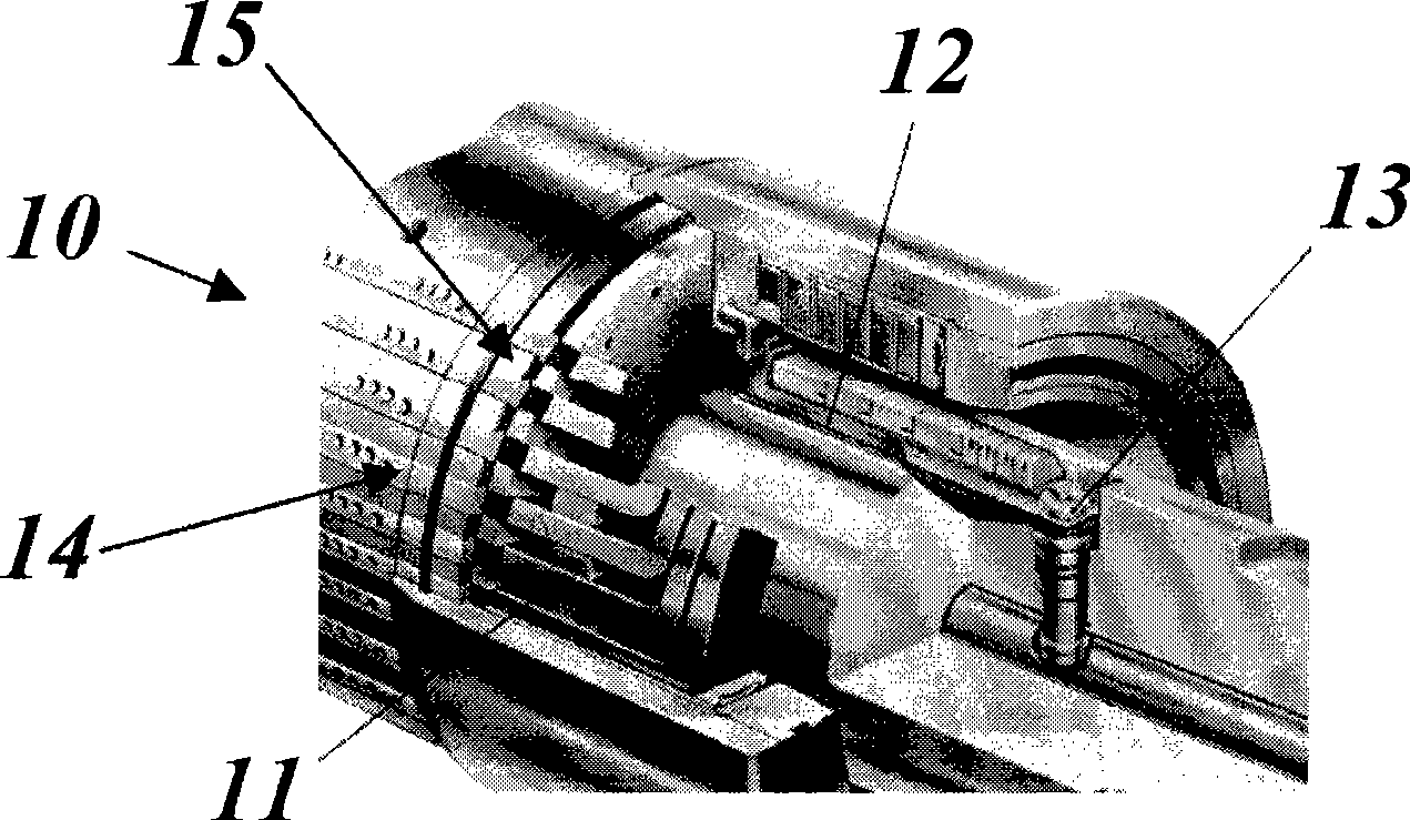
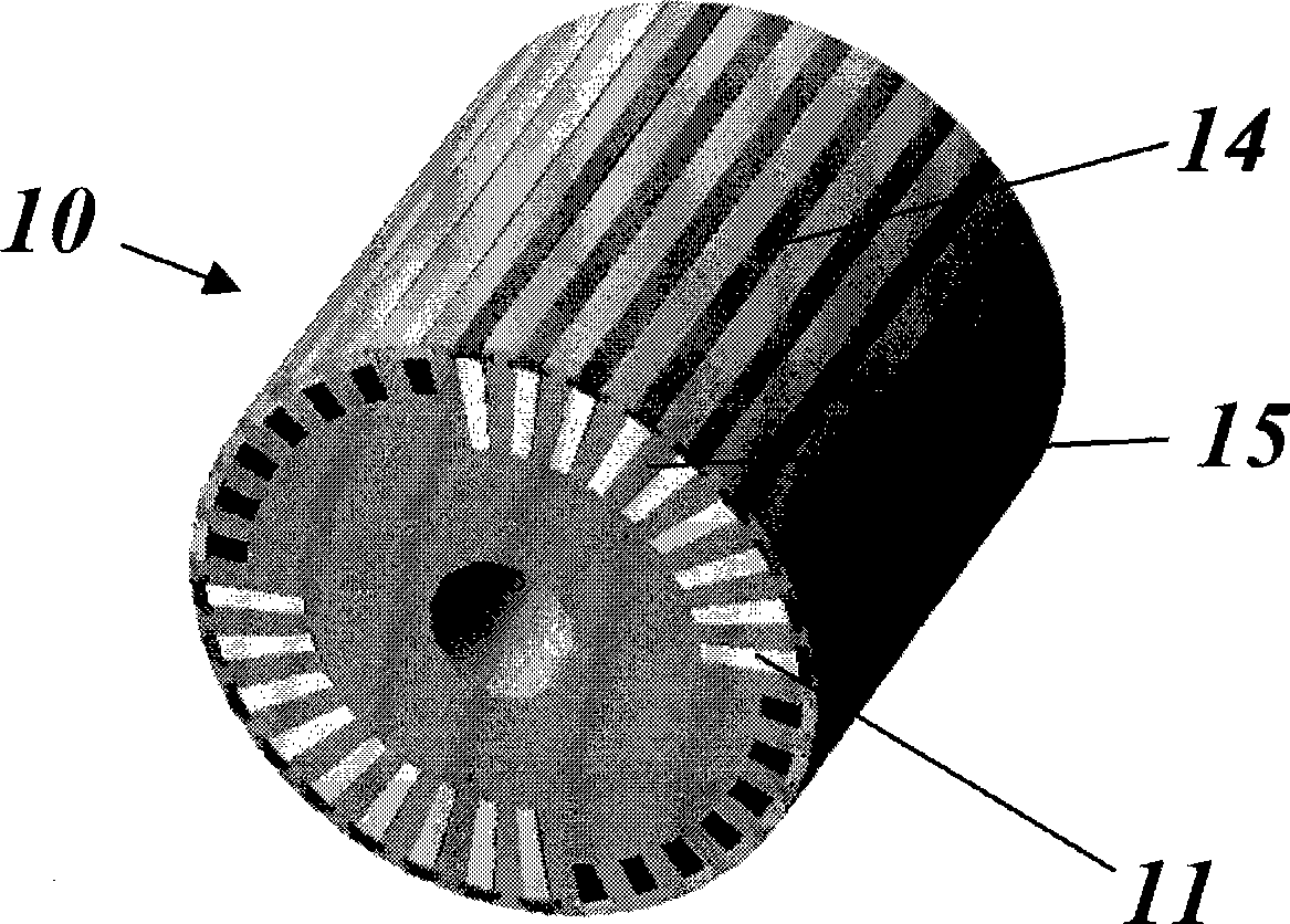
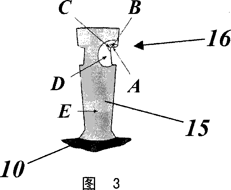
[0037] Not only is the new method capable of detecting wear cracks inside the assembled rotor, it has also proven to be compact enough for field measurements, i.e. it fits in the limited space of the air gap between the rotor and stator, thus allowing condition assessment of the generator rotor, even There is no need to remove the rotor from the stator.

[0038] The new method and device can be easily applied to existing deployment robots and institutions.

[0039] The new method and device are especially capable of preventing catastrophic failures due to cracks caused by aging.

[0040] The proposed system for inspecting generator rotors consists of an array of pulse-echo ultrasonic transducers (see Figure 5 18) in , which provides a range of active elements, with special ...


PUM


Abstract

Provided is a method and an apparatus for the detection of cracks in the teeth of generator rotors. The method for non-destructive testing the teeth of a high power electrical generator rotor includes the steps of: providing a plurality of ultrasonic pulse echo transducers (22, . . . ,25) being arranged in an array (20), and being positioned and aligned in such a way as to provide a range of different inspection angles for the tooth geometry; positioning the array (20) on top of the rotor tooth; exciting at least one of the plurality of ultrasonic pulse echo transducers (22, . . . ,25) to produce a transmission beam for the interrogation of wedge angle on the underside of the tooth; and conditioning the acquired data from the at least one of the plurality of ultrasonic pulse echo transducers (22, . . . ,25) to capture reflection from the flaws within the tooth.

Description

technical field [0001] The present invention generally relates to high power generators. In particular, the present invention relates to methods and apparatus for detecting cracks in generator rotor teeth. Background technique [0002] The generator rotor is manufactured from forged steel and has radial slots machined along the length of the shaft. These radial slots engage the conductors for the field windings to generate the required magnetic fields for power generation. This conventional field winding is confined in slots by wedges. These wedges are usually dovetail arrangements, but may vary in design depending on the rotor design. The copper conductor blocks are held in place by slot wedges as the rotor turns. [0003] Rotor tooth cracks due to wear between the steel wedge and the rotor during low speed barring (loose wedge) have been reported in the past. Such defects seem to occur frequently, so NDT (non-destructive testing) methods have been developed to allow d...

Claims


Application Information

Patent Timeline
Patent Type & Authority Applications(China)
IPC IPC(8): G01N29/04
CPCG01N2291/104G01N29/11G01N29/265G01N2291/263G01N2291/044G01N2291/2693
Inventor J·诺尔斯R·莫瑟
Owner ALSTOM TECH LTD
Why Eureka
Try Eureka