Medium high voltage anode aluminum foil corrosion method

An anode aluminum foil, medium and high voltage technology, applied in the direction of electrical components, electrolytic capacitors, capacitors, etc., can solve the problems of reduced service life of products, difficulty in removing metal impurities, etc., and achieve the effect of high production efficiency

Inactive Publication Date: 2009-05-06
DONGGUAN HEC CONDENSER CO LTD
View PDF1 Cites 19 Cited by
  • Summary
  • Abstract
  • Description
  • Claims
  • Application Information

AI Technical Summary

Benefits of technology

This patented technology allows for efficient creation of pores by treating solutions with different acids at once without wasting too much time on each step. It can be used even after being treated twice before disposal.

Problems solved by technology

This patented technical problem addressed in the present describes how to improve the performance (volume) or lifespan of anodes in electric double layer condensers without causing contamination during manufacturing processes such as etching.

Method used


Image

  • Medium high voltage anode aluminum foil corrosion method

Examples


Embodiment 1

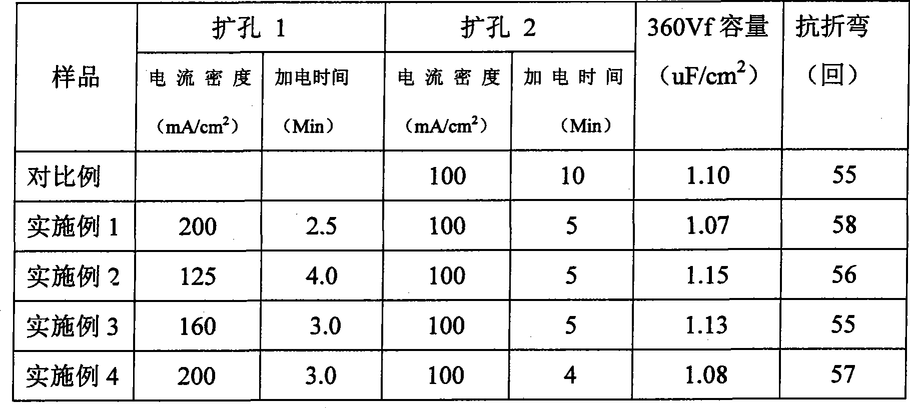
[0027] Hole expansion corrosion is divided into two steps, the first current density is 200mA / cm 2 , the bath is 4% nitric acid, corroded for 2.5 minutes, and the current density of the second step of hole expansion is 100mA / cm 2 , the bath solution is 2% nitric acid, corroded for 5 minutes, and other processes include pre-treatment, corroding and post-treatment, which are the same as those of the comparative example.

Embodiment 2

[0029] Hole expansion corrosion is divided into two steps, the first current density is 125mA / cm 2 , the bath solution is 4% nitric acid, corroded for 4 minutes, and the current density of the second step of hole expansion is 100mA / cm 2 , the bath solution is 2% nitric acid, corroded for 5 minutes, and other processes include pre-treatment, corroding and post-treatment, which are the same as those of the comparative example.

Embodiment 3

[0031] Hole expansion corrosion is divided into two steps, the first current density is 160mA / cm 2 , the bath solution is 4% nitric acid, corroded for 3 minutes, and the current density of the second step of hole expansion is 100mA / cm 2 , the bath solution is 2% nitric acid, corroded for 5 minutes, and other processes include pre-treatment, corroding and post-treatment, which are the same as those of the comparative example.


PUM


Abstract

The invention relates to the technical field of electrolytic capacitors, in particular to a corrosion method of middle-high-voltage anode aluminum foil. The corrosion method comprises two electrochemical corrosion processes of pitting corrosion and pore-enlarging corrostion, wherein the pitting corrosion is carried out in a mixed solution of hydrochloric acid and acid which can generate filam, and the pore-enlarging corrosion is carried out in hydrochloric acid solution or nitric acid solution and is completed by two steps. The invention has a plurality of advantages of high production efficiency, energy conservation, environmental protection, and the like.

Description


Claims


Application Information

Patent Timeline
Owner DONGGUAN HEC CONDENSER CO LTD
Why Eureka
Try Eureka