Method and device for coupling cancellation of closely spaced antennas

A technology for antenna elements and antenna systems, applied in the field of radiating elements and their respective reference ports, which can solve problems such as impracticality

Inactive Publication Date: 2009-05-06
TELEFON AB LM ERICSSON (PUBL)
View PDF1 Cites 9 Cited by
  • Summary
  • Abstract
  • Description
  • Claims
  • Application Information

AI Technical Summary

Problems solved by technology

This is impractical to implement in a handheld terminal

Method used


Image

  • Method and device for coupling cancellation of closely spaced antennas
  • Method and device for coupling cancellation of closely spaced antennas
  • Method and device for coupling cancellation of closely spaced antennas

Examples


Embodiment Construction

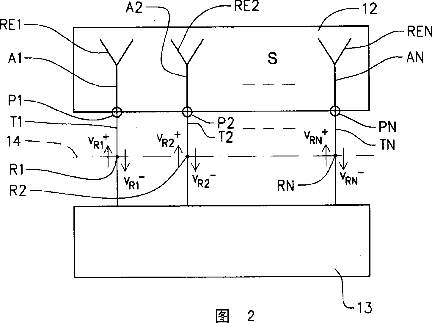
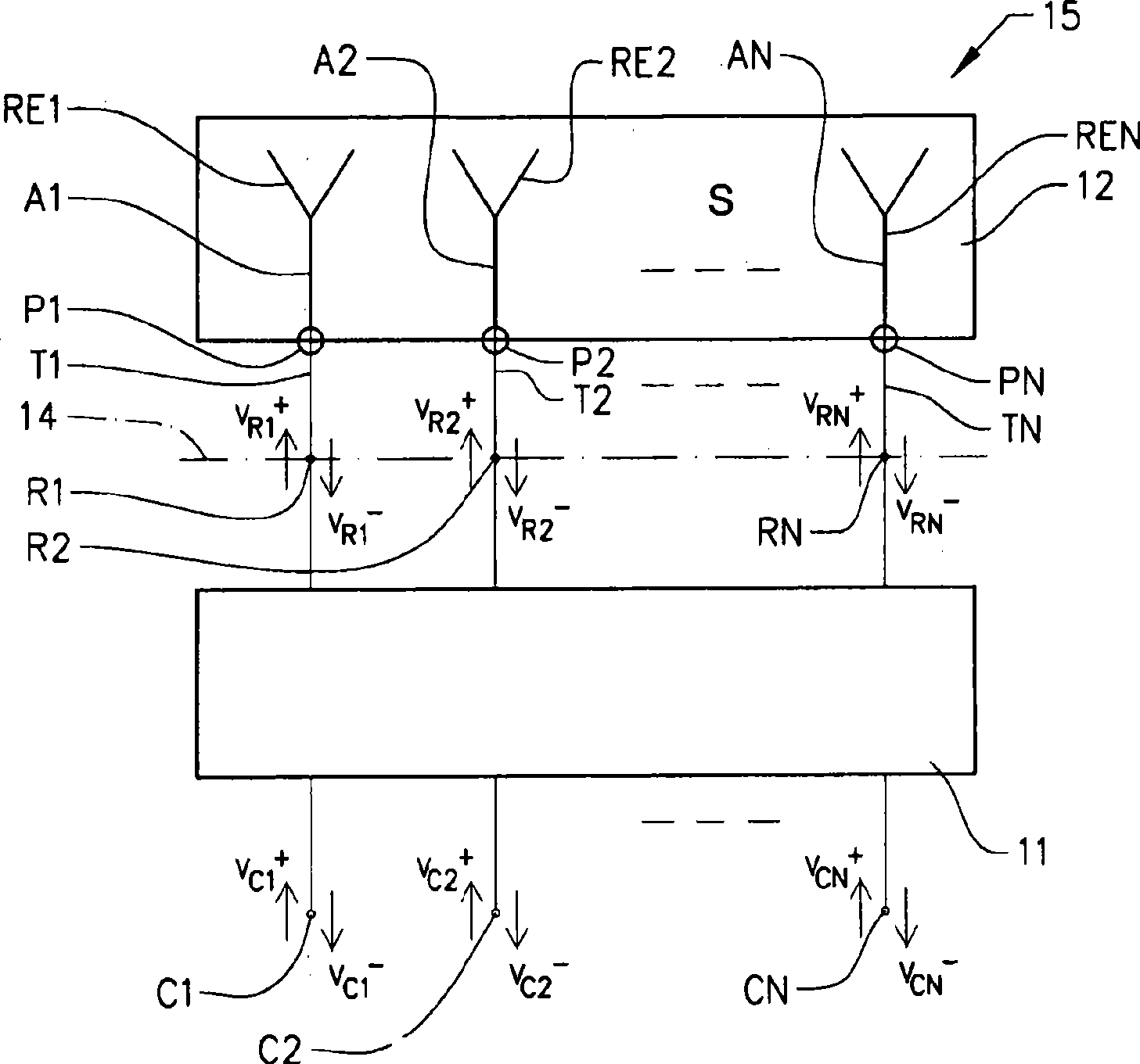
[0034] In a general lossless multiple-antenna system with N ports, the power of the signal received or transmitted by antenna port i is reduced by a factor of 1 minus the sum of the squared magnitudes of the scattering coefficients associated with that port.

[0035] P i = 1 - Σ j = 1 N | S ji | 2 - - - ( 1 )

[0036] In the case of transmission, this relationship is quite pronounced, since reflected and coupled power is absorbed in the load of the port. However, due to reciprocity, this relationship also holds when the antenna system is used for reception. Instead of being received by the other antenna ports, the energy of t...


PUM


Abstract

The present invention relates to an antenna system (15) comprising at least two antenna radiating elements (RE1, RE2,..., REN) and respective reference ports (R1, R2,..., RN), the ports being defined by a symmetrical antenna scattering NxN matrix (S). The system (15) further comprises a compensating network (11) connected to the reference ports (R1, R2,..., RN). The compensating network (11) is arranged for counteracting coupling between the antenna radiating elements (A1, A2..., AN). The compensating network (11) is defined by a symmetrical compensating scattering 2Nx2N matrix (Sc) comprising four NxN blocks, the two blocks on the main diagonal containing all zeros and the other two blocks of the other diagonal containing a unitary NxN matrix (V) and its transpose (Vt). The product between the unitary matrix (V), the scattering NxN matrix (S) and the transpose (Vt) of the unitary matrix (V) equals an NxN matrix (s) which essentially is a diagonal matrix. The present invention also relates to a method for calculating a compensating scattering 2Nx2N matrix (Sc) for a compensating network (11) for an antenna system according to the above, and also to a compensating network (11) for an antenna system according to the above.

Description

technical field [0001] The present invention relates to an antenna system comprising at least two antenna elements having respective radiating elements and respective reference ports defined by a symmetric antenna dispersion N x N matrix, the system further comprising being arranged with These reference ports are connected and have a corresponding compensation network of at least two network ports arranged to cancel the coupling between the antenna radiating elements. [0002] The invention also relates to a method for calculating a compensation scatter 2N x 2N matrix for a compensation network for an antenna system comprising at least two antenna elements with respective radiating elements and respective reference ports, wherein The compensation network is arranged to be connected to the reference ports and has corresponding at least two network ports, the compensation network is arranged to cancel the coupling between antenna radiating elements, wherein the method comprises ...

Claims


Application Information

Patent Timeline
Patent Type & Authority Applications(China)
IPC IPC(8): H01Q1/52H01Q21/28
CPCH01Q1/52H01Q21/28H01Q21/00
Inventor A·德纳伊德A·斯特杰恩曼
Owner TELEFON AB LM ERICSSON (PUBL)
Why Eureka
Try Eureka