Swing switch structure of water exit apparatus

一种出水装置、切换装置的技术,应用在喷射装置、喷射装置等方向,能够解决操作不便、旋转力矩大等问题

Inactive Publication Date: 2009-05-13
XIAMEN SOLEX HIGH TECH IND CO LTD
View PDF0 Cites 28 Cited by
  • Summary
  • Abstract
  • Description
  • Claims
  • Application Information

AI Technical Summary

Problems solved by technology

The selection of various water outlets is achieved by rotating the cover of the shower head relative to the water inlet hole of the water divider in the shower head into different water inlet chambers of the cover, so the switching structure must be operated with both hands at the same time. , and the hand holding the face cover will inevitably come into contact with the water flow, and the rotation torque is large, so it will be slightly inconvenient to operate

Method used


Image

  • Swing switch structure of water exit apparatus
  • Swing switch structure of water exit apparatus
  • Swing switch structure of water exit apparatus

Examples


Embodiment 1

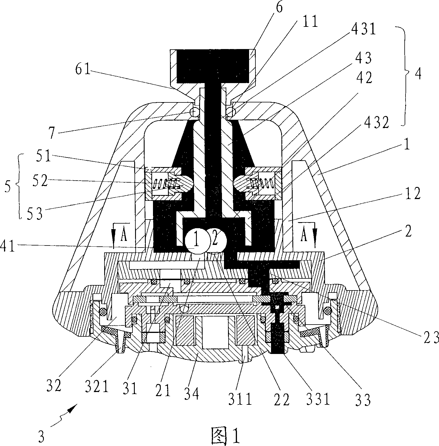
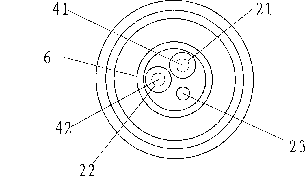
[0024] As shown in FIGS. 1 , 2 and 3 , the swing switching structure includes a shower body 1 , a water diversion body 2 , a water outlet device 3 and a movable switching device 4 , and also includes a reset mechanism 5 .

[0025] The shower body 1 is a trumpet-shaped shell, the water outlet device 3 is fixed at its lower part, the water diversion body 2 is fixed above the water outlet device 3, and the water inlet 11 at the upper end of the shower body 1 is movably connected with the water supply pipe joint 6. The movable switching device 4 is located above the water diversion body 2, and the upper end of the movable switching device 4 is fixedly connected with the water supply pipe joint 6 from the water inlet 11 of the shower body 1; a cylinder 12 is formed above the shower body 1 , the movable switching device 4 is located in the cylinder 12, and the water diversion body 2 cooperates with the lower part of the cylinder 12.

[0026] The upper surface of the water distributi...

Embodiment 2

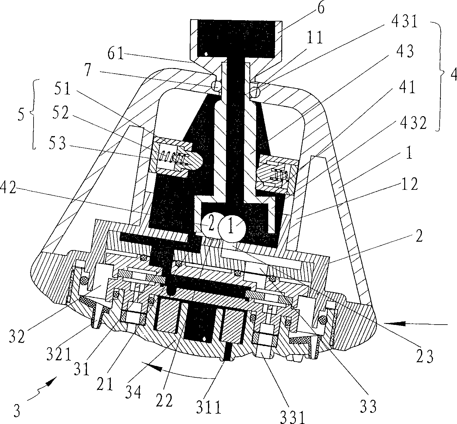
[0037] Such as Figure 4 , 5 , 6, another embodiment of the swing switching structure, which also includes a shower body 1, a water diversion body 2', a water outlet device 3' and a movable switching device 4', and also includes a reset mechanism 5.

[0038] The shower body 1 is a trumpet-shaped shell, the water outlet device 3 is fixed at its lower part, the water distribution body 2 is fixed above the water outlet device 3, and the water inlet 11 at the upper end of the shower body 1 is movably connected with the water supply pipe joint 6. The movable switching device 4 is located above the water diversion body 2, and the upper end of the movable switching device 4 is fixedly connected with the water supply pipe joint 6 from the water inlet 11 of the shower body 1; a cylinder 12 is formed above the shower body 1 , the movable switching device 4 is located in the cylinder 12, and the water diversion body 2 cooperates with the lower part of the cylinder 12.

[0039] Two bump...


PUM


Abstract

The invention relates to a swing switching structure of a water outlet device, which comprises a sprinkler body, a water distributing body and a water outlet device, wherein, the water outlet device is fixed below the sprinkler body; the water distributing body is fixed above the water outlet device in a sealing manner; at least two water distributing holes are formed on the water distributing body for respectively communicating every functional water cavity of the water outlet device; and a movable switching device is arranged above the water distributing body of the sprinkler body, passes through the sprinkler body and is fixed to a water supplying joint. When the sprinkler body swings relative to the movable switching device, the movable switching device can plug water distributing holes formed on the distributing body and keep one water distributing hole in an open state. Through the arrangement of the movable switching device on the sprinkler in combination with the clearance fit relation between the sprinkler and a water supply pipe joint, the sprinkler can be swung and inclined when being flapped and the movable switching device can control the water outlets of different water distributing holes on the water distributing body, thereby realizing the switching of various functional waters, and enabling the switching of the sprinkling functional waters to be more laborsaving and flexible.

Description

technical field [0001] The invention relates to a shower device, in particular to a swing switching structure of a water outlet device. Background technique [0002] At present, the shower is no longer a single function of spraying water. It can form a variety of spray functions through different water inlet chambers in the cover and different water outlet holes, such as sparkling water, massage water or shower water. The choice of various water outlets can be switched by rotating the face cover of the shower relative to the water inlet hole of the water diversion body in the shower and entering different water inlet chambers of the face cover. Such a switching structure must be operated with both hands at the same time. , and the hand holding the face cover will inevitably come into contact with the water flow, and the rotation torque is large, so there will be a slight sense of inconvenience during operation. Contents of the invention [0003] The purpose of the present...

Claims


Application Information

Patent Timeline
Patent Type & Authority Applications(China)
IPC IPC(8): B05B1/16B05B15/68
CPCB05B1/1609B05B1/18B05B15/067B05B1/1618B05B1/302B05B1/169B05B15/654
Inventor 陈健民李仁忠
Owner XIAMEN SOLEX HIGH TECH IND CO LTD
Why Eureka
Try Eureka