
Video projection system

A technology of projection device and projection mirror, which is applied in the direction of projection device, instrument, color TV parts, etc., can solve the problems of damage, inversion, wrong inversion, etc., and achieve the effect of reducing negligent damage and reducing external force

Inactive Publication Date: 2009-05-20
MAXELL HLDG LTD
View PDF2 Cites 5 Cited by
  • Summary
  • Abstract
  • Description
  • Claims
  • Application Information

AI Technical Summary

Problems solved by technology

[0008] In addition, when moving the projection device, there are cases where it is mistakenly turned upside down
That is, in the conventional technology, the projection mirror may be damaged or damaged due to the upside down due to the user's negligence.

Method used


Image

  • Video projection system
  • Video projection system
  • Video projection system

Examples


Embodiment Construction

[0023] Hereinafter, preferred modes for carrying out the present invention will be described with reference to the drawings. In all the drawings, components having common functions are denoted by the same symbols, and in order to avoid complexity, repeated descriptions of matters explained once are omitted. Hereinafter, a liquid crystal panel will be used as an image display element for description, but the present invention is not limited thereto.

[0024] The present invention is characterized by having a roller bar that prevents damage to the projection mirror provided on the outer wall surface of the housing when the projection device is turned upside down.

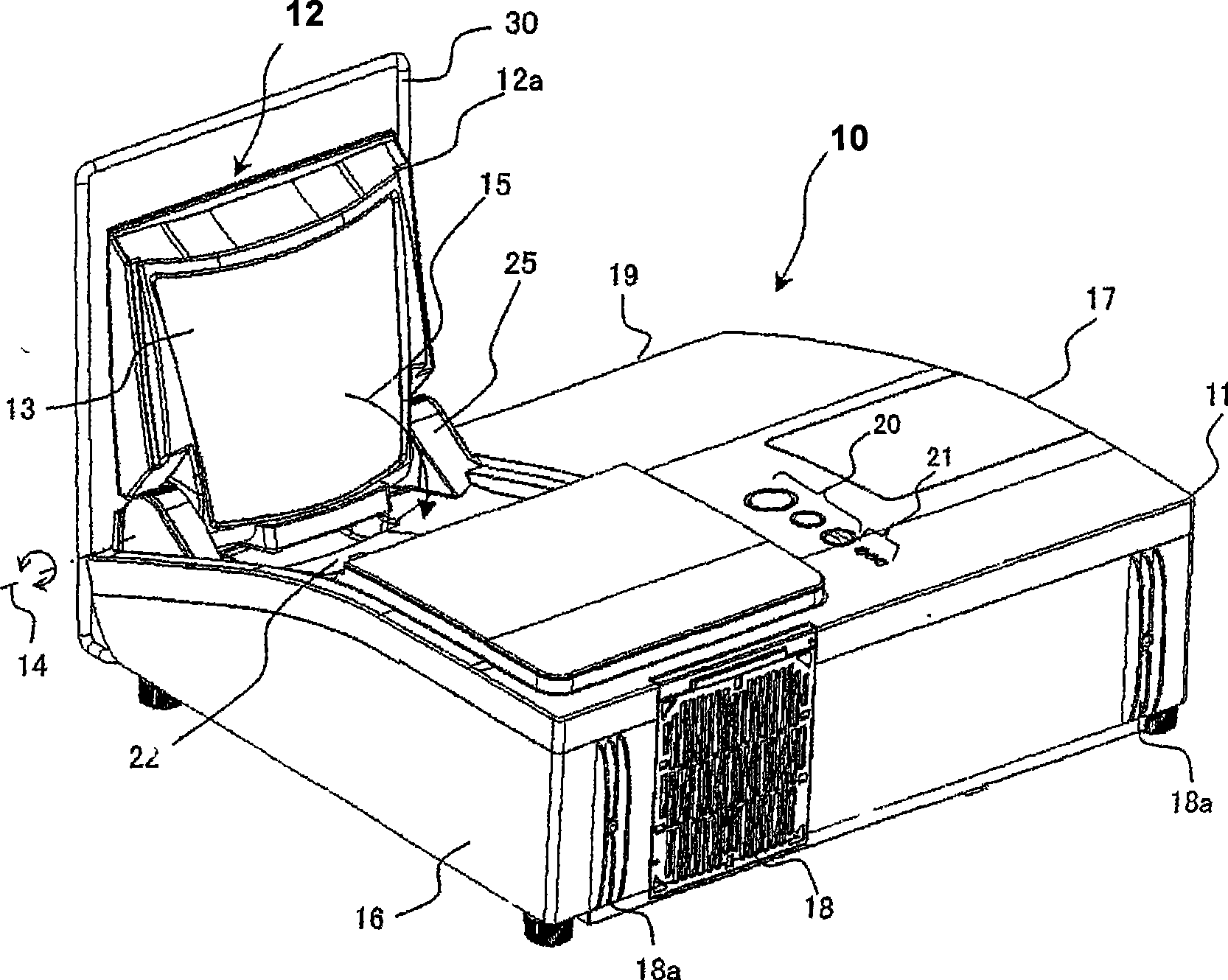
[0025] figure 1 It is an external perspective view of the projection device of this embodiment, showing a state in which the projection mirror is pulled up and fixed at a fixed position for operation.

[0026] Such as figure 1 As shown, the projection device 10 of this embodiment has a frame body 11, a projection m...


PUM


Abstract

The invention relates to a projector apparatus with a projection mirror that does not damaged by defect turnover of the user with a protection projection mirror on a mechanism. Further the defect turnover can be reduced with great carrying property in condition of a mobile apparatus. A roll bar for protecting a projection mirror is attached so as to avoid exerting an external force to the projection mirror portion. Further, in the case of no attachment of the roll bar for protecting the projection mirror portion, the projector apparatus is prevented from being started. Further, when the projector apparatus is carried away, the roller bar for protecting the projection mirror serves as a handle.

Description

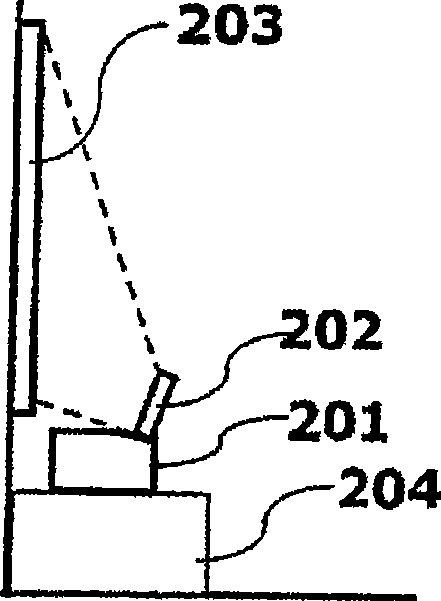
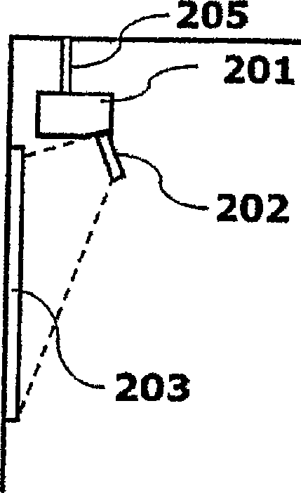
technical field [0001] The present invention relates to technology for providing a projection device. Background technique [0002] A projection device uses an image display element such as a liquid crystal panel to modulate the light emitted from a light source according to an image signal to form an optical image (referred to as an image), and uses a projection lens or a projection mirror to project the optical image on an external screen or wall, etc. on the irradiated surface. In recent projection devices, when projecting on an irradiated surface such as an external screen, the number of projectors that make the distance to the irradiated surface (projection display distance) very short (see Patent Document 1, Patent Document 2) . [0003] Patent Document 1 to Patent Document 2 describe the following projection devices, such as Patent Document 2 figure 1 As shown, the display light of the image (optical image) formed by the image display element inside the housing mod...

Claims


Application Information

Patent Timeline
Patent Type & Authority Applications(China)
IPC IPC(8): G03B21/00G03B21/14G03B21/28
CPCH04N9/3141G03B21/30
Inventor 齐藤刚
Owner MAXELL HLDG LTD
Learn More