
A modular pressure relief assembly capable of automatic pressure relief

A pressure relief component, modular technology, applied in the direction of engine components, valve devices, safety valves, etc., can solve the problem that the pressure in the liquid cooling equipment cannot be completely relieved, the liquid cooling system of the liquid cooling equipment fails, and the structure, volume and shape are inconsistent. The same problem, to achieve the effect of reducing the phenomenon of bursting damage, compact structure, and improving stability and reliability

Active Publication Date: 2021-12-03
CHINA AVIATION OPTICAL-ELECTRICAL TECH CO LTD
View PDF0 Cites 0 Cited by
  • Summary
  • Abstract
  • Description
  • Claims
  • Application Information

AI Technical Summary

Problems solved by technology

[0002] As is known, during the operation or debugging of the liquid cooling system, it is often necessary to maintain the liquid cooling equipment in the system. After the shutdown, the pressure in the liquid cooling equipment may not be completely relieved. As the ambient temperature rises, the liquid inside the equipment expands due to heat, and the pressure increases sharply, which is enough to overpressure and damage the liquid cooling equipment; when the liquid cooling system operates at the rated pressure, the system may experience unstable supply pressure. At the safe pressure, if the liquid cooling system is always in a closed state, the sudden pressure will cause overpressure damage to the system; in the above two application environments, the internal pressure of the liquid cooling equipment rises sharply, because the liquid cooling system is always in a closed state, As a result, the pressure cannot be discharged in time, and the overpressure will cause the failure of the liquid cooling equipment or the entire liquid cooling system; at present, the liquid cooling system mostly uses a pressure relief valve or a fluid connector with automatic pressure relief to solve the harm caused by the system overpressure. However, various pressure relief valves or fluid connectors with automatic pressure relief have complex structures and large volumes, especially when the pressure relief pressure values ​​are different, the structure, volume, and shape are not the same; in addition, due to the miniaturization of the liquid cooling system, Lightweight requirements, under the premise of ensuring functional performance, the smaller the pressure relief component, the better the structure

Method used


Image

  • A modular pressure relief assembly capable of automatic pressure relief
  • A modular pressure relief assembly capable of automatic pressure relief

Examples


Embodiment Construction

[0016] The present invention can be explained in detail through the following examples, and the purpose of disclosing the present invention is to protect all technical improvements within the scope of the present invention.

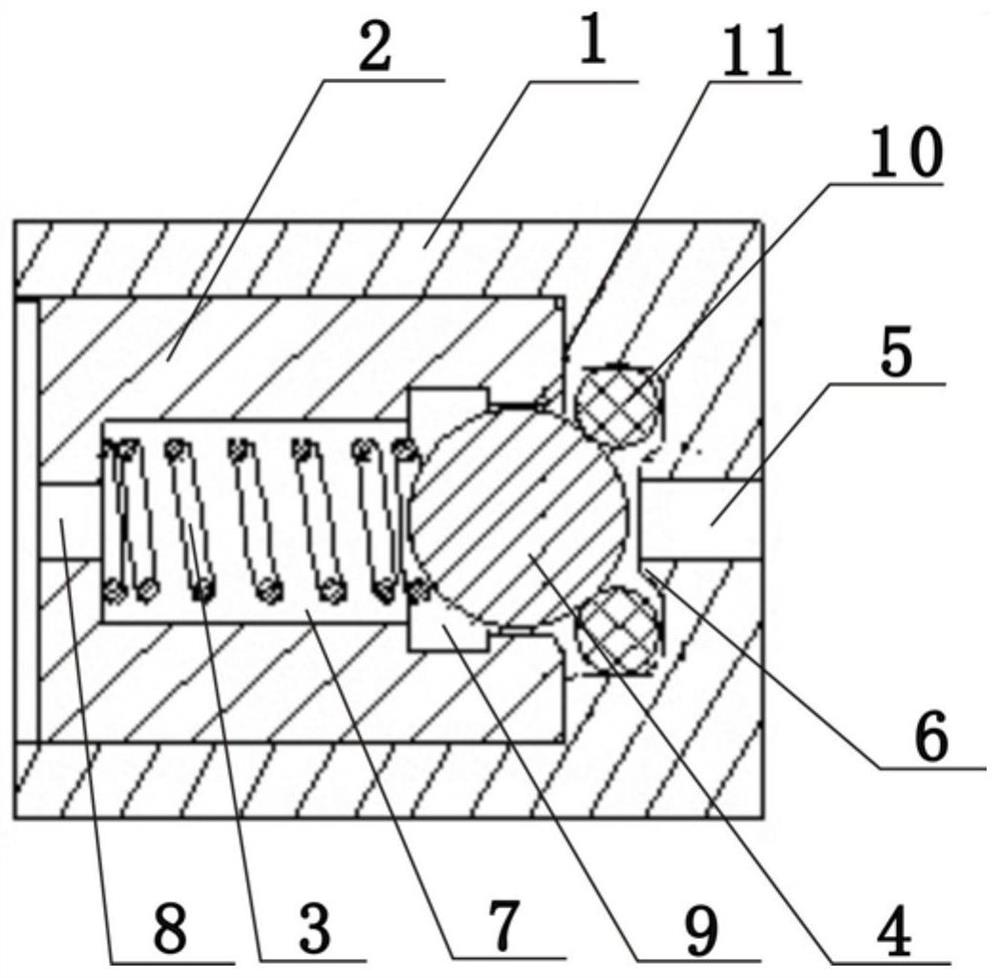
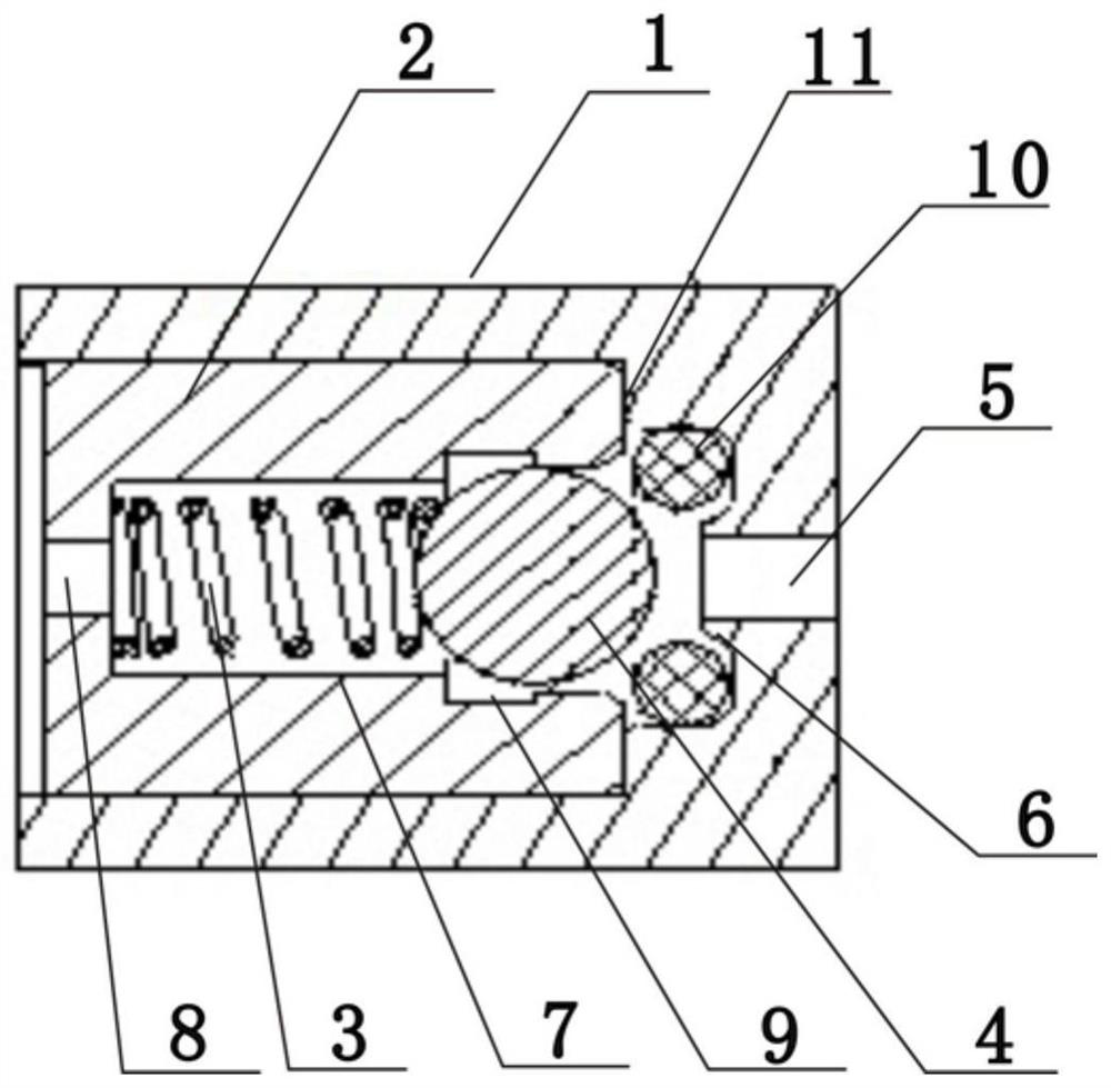
[0017] combined with Figure 1~2 , a modular pressure relief assembly that can automatically relieve pressure, including a housing 1, a positioning block 2, a spring 3 and a ball 4; the housing 1 is hollow inside, and one end is open, and the other end of the housing 1 A through hole 5 corresponding to the internal cavity is provided, and an annular boss 6 coaxial with the through hole 5 is provided at the position corresponding to the through hole 5 in the cavity of the housing 1; the inner sealing device of the open end of the housing 1 There is a positioning block 2; as required, the outer wall of the positioning block 2 is connected to the inner wall of the cavity of the housing 1 by corresponding threads, the structure is simple, easy to assemble, an...


PUM


Abstract

A modular pressure relief assembly capable of automatic pressure relief, which relates to the technical field of sealing and pressure relief in liquid cooling systems, is characterized in that it includes a housing, positioning blocks, springs and balls; the housing is hollow inside, and One end is open, and the other end of the housing is provided with a through hole corresponding to the internal cavity, and the position of the corresponding through hole in the housing cavity is provided with an annular boss coaxial with the through hole; the opening of the housing The inner seal of the end is provided with a positioning block, and one end of the positioning block corresponding to the through hole is provided with a pressure relief chamber, and the other end of the positioning block is provided with a drain hole corresponding to the pressure relief chamber, and the mouth of the pressure relief chamber The edge is movably connected with balls, and the pressure relief chamber is provided with springs at both ends that are respectively in conflict with the bottom of the pressure relief chamber and the balls. Such pressure relief valves or fluid connectors with automatic pressure relief have complex structures and large volumes.

Description

technical field [0001] The invention relates to the technical field of sealing and pressure relief in a liquid cooling system, in particular to a modular pressure relief assembly capable of automatic pressure relief. Background technique [0002] As is known, during the operation or debugging of the liquid cooling system, it is often necessary to maintain the liquid cooling equipment in the system. After the shutdown, the pressure in the liquid cooling equipment may not be completely relieved. As the ambient temperature rises, the liquid inside the equipment expands due to heat, and the pressure increases sharply, which is enough to overpressure and damage the liquid cooling equipment; when the liquid cooling system operates at the rated pressure, the system may experience unstable supply pressure. At the safe pressure, if the liquid cooling system is always in a closed state, the sudden pressure will cause overpressure damage to the system; in the above two application envi...

Claims


Application Information

Patent Timeline
Patent Type & Authority Patents(China)
IPC IPC(8): F16K17/04F16K17/164F16K1/46
CPCF16K1/46F16K17/0406F16K17/164
Inventor 冯亚利谢地蔡艳召李俊阳曹海军
Owner CHINA AVIATION OPTICAL-ELECTRICAL TECH CO LTD
Learn More