Power line DC ice-melting device

A technology for DC ice melting and power transmission lines, which is applied in cable installation, electrical components, overhead installation, etc., to achieve the effect of unimpeded ice melting work, eliminating the need for line connection and load transfer, and reducing safety risks

Inactive Publication Date: 2009-05-20
STATE GRID HUNAN ELECTRIC POWER CO LTD ELECTRIC POWER SCI RES INST +1
View PDF0 Cites 6 Cited by
  • Summary
  • Abstract
  • Description
  • Claims
  • Application Information

AI Technical Summary

Problems solved by technology

[0003] The technical problem to be solved by the present invention is to design a DC deicing device for power transmission lines that can be used in combination in view of the backwardness of the existing technology, and use the device to perform deicing treatment on the power transmission lines after ice coating to reduce on-site dumping. Gate operation to avoid grid load transfer

Method used


Image

  • Power line DC ice-melting device
  • Power line DC ice-melting device

Examples


Embodiment 1

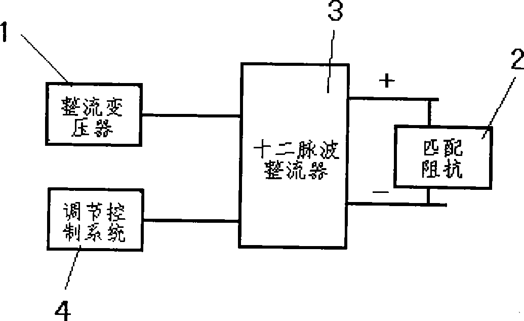
[0021] Embodiment 1: The DC deicing device for transmission lines that can be used in combination in this embodiment of the present invention, such as figure 1 As shown, the rectifier transformer 1 adopts ZS-4600 / 10 type rectifier transformer with a capacity of 4600kVA produced by China Hengyang TBEA Hengyang Transformer Co., Ltd.; its matching impedance 2 adopts R1000 type impedance produced by Hunan Huicui Power Technology Co., Ltd. Matching device; 12-pulse rectifier 3 selects the KYAF-1400 / 3000 type jointly developed by China Hunan Huicui Power Technology Co., Ltd. A rectifier with a current of 2000A; its regulation control system 4 is also a HDC-2008 control system developed by China Hunan Huicui Power Technology Co., Ltd. The above-mentioned rectifier transformer 1, matching impedance 2, twelve-pulse rectifier 3 and adjustment control system 4 are pressed figure 1 Circuit composition shown. Wherein the rectifier transformer 1 and the regulation control system 4 are con...

Embodiment 2

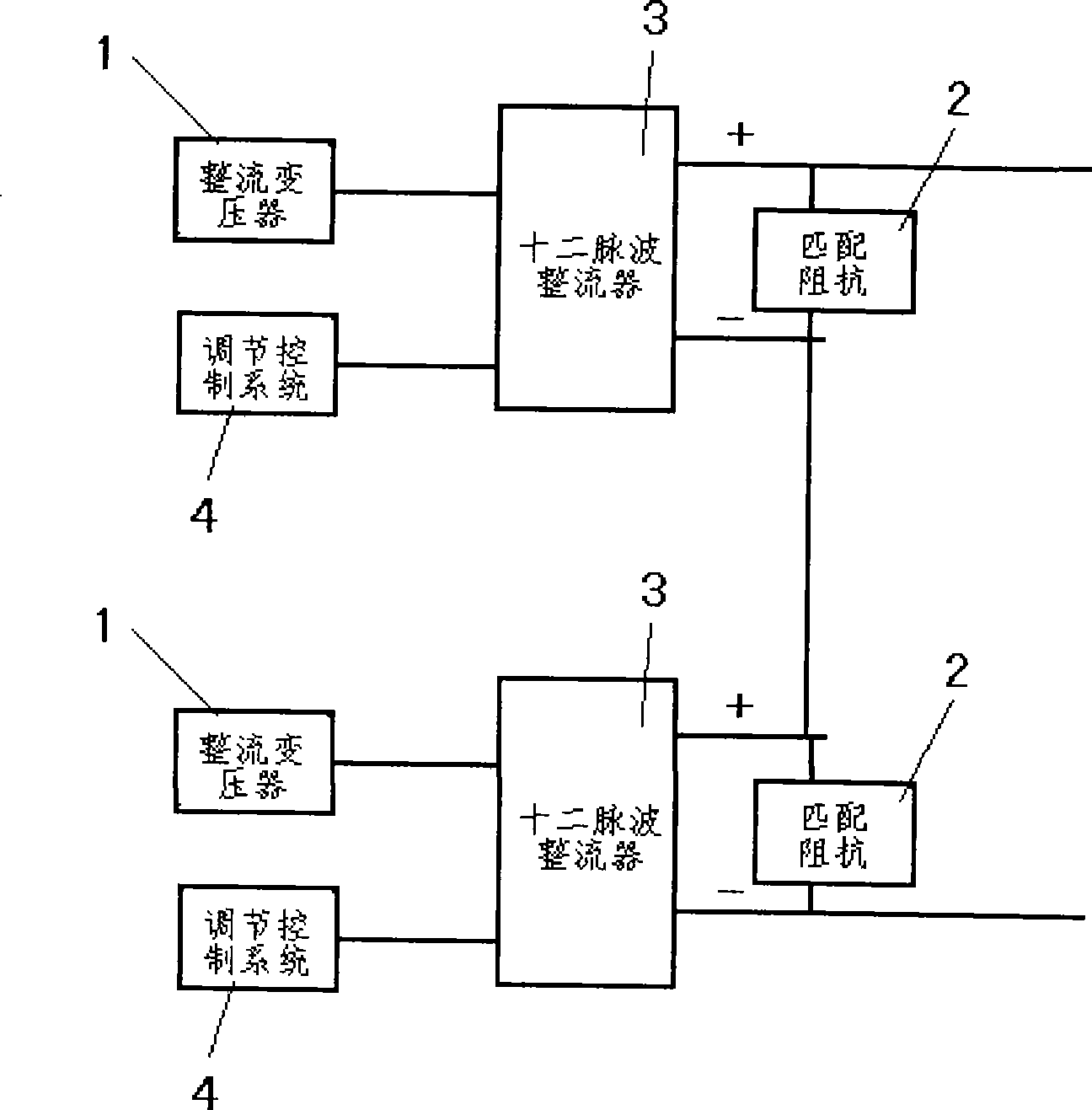
[0022] Embodiment 2: The rectifier transformer 1 of this embodiment adopts the ZSC9-4600 / 10.5 / 2×1.2 type rectifier transformer produced by China Dongguan Shunte Electric Co., Ltd. The matching impedance 2, the twelve-pulse rectifier 3 and the adjustment control system 4 are the same as those in the first embodiment. The connections among the rectifying transformer 1, matching impedance 2, twelve-pulse rectifier 3 and regulation control system 4 are also the same as those in the first embodiment. But in the present embodiment, there are two DC deicing devices for power transmission lines that can be used in combination, and these two devices are used in combination, and their combined connection methods are as follows: figure 2 The circuit shown is connected in a simple way, just connect the positive pole / negative pole of the twelve-pulse rectifier 3 of one device with the negative pole / positive pole of the twelve-pulse rectifier 3 of the other device.


PUM


Abstract

The invention discloses a transmission line DC deicing device which can be used in combination. The device consists of a rectifier transformer (1), a matched resistor (2), a 12-pulse rectifier (3) and a regulation and control system (4), wherein the rectifier transformer (1) and the regulation and control system (4) are parallelly and electrically connected with the input end of the 12-pulse rectifier (3). Two ends of the matched resistor (2) are connected with a cathode and an anode of the output end of the 12-pulse rectifier (3) respectively. When a transmission line is covered with ice, the rectifier transformer 1 is accessed to a power grid to convert a three-phase alternating-current supply to a DC power supply and apply the DC power supply to the transmission line, and uses the heat generated by a conducting wire electrified to melt the ice. A plurality of sets of transmission line DC deicing devices can be serially connected to adapt to deicing of transmission lines with different lengths, and can reduce capacity of the power supply, reduce security risks, achieve smooth deicing operation and deice transmission line within 30 kilometers each time.

Description

technical field [0001] The invention belongs to the technical field of electrical engineering, and in particular relates to a DC deicing device for power transmission lines that can be used in combination. The device is suitable for carrying out DC deicing treatment on power transmission lines after ice coating, so as to avoid disconnection of power transmission lines after ice coating Even a tower collapse accident. Background technique [0002] In recent years, severe accidents of transmission line disconnection or even tower collapse due to icing have occurred frequently. For example, the power grid ice disaster that occurred in Hunan Province, China in January 2008 caused a large number of transmission lines to collapse and disconnect, causing direct economic losses of billions of yuan and seriously affecting the safe operation of the power grid and the normal life of the people. Therefore, it is very necessary to timely melt the ice when the transmission line forms ice...

Claims


Application Information

Patent Timeline
Patent Type & Authority Applications(China)
IPC IPC(8): H02G7/16
Inventor 陆佳政李波方针张红先
Owner STATE GRID HUNAN ELECTRIC POWER CO LTD ELECTRIC POWER SCI RES INST
Why Eureka
Try Eureka