
Bottle pushing apparatus

A technology of glass bottles and cylinders, which is applied in packaging, packaging bottles, transportation and packaging, etc. It can solve the problems of inability to perform complex or special actions, affecting the speed of products being put on the market, and the difficulty of automatic completion of the bottle pushing device. Achieve fast and smart bottling process, reduce packing space, reasonable and practical overall structure

Inactive Publication Date: 2011-07-13
宁波正力药品包装有限公司
View PDF0 Cites 2 Cited by
  • Summary
  • Abstract
  • Description
  • Claims
  • Application Information

AI Technical Summary

Problems solved by technology

[0002] In order to put the glass bottles into the packaging box, the general factory adopts manual operation, which results in low work efficiency and poor automation, which affects the speed of products being put on the market. Therefore, a bottle pushing device is needed to automatically complete the boxing work.
[0003] The existing bottle pushing device can only perform some simple actions, which can push the vertical glass bottle in the working surface, but cannot perform some more complicated or special actions
Common glass bottles are generally cylindrical. When packing, in order to reduce the packing space, the arrangement is more compact and easy to transport. Usually, after packing, the glass bottles in two adjacent rows are staggered by half the diameter of the bottle. However, It is difficult for the existing bottle pushing device to automatically complete this process when packing the box

Method used


Image

  • Bottle pushing apparatus
  • Bottle pushing apparatus
  • Bottle pushing apparatus

Examples


Embodiment

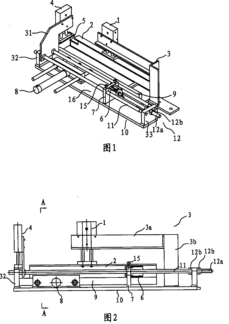
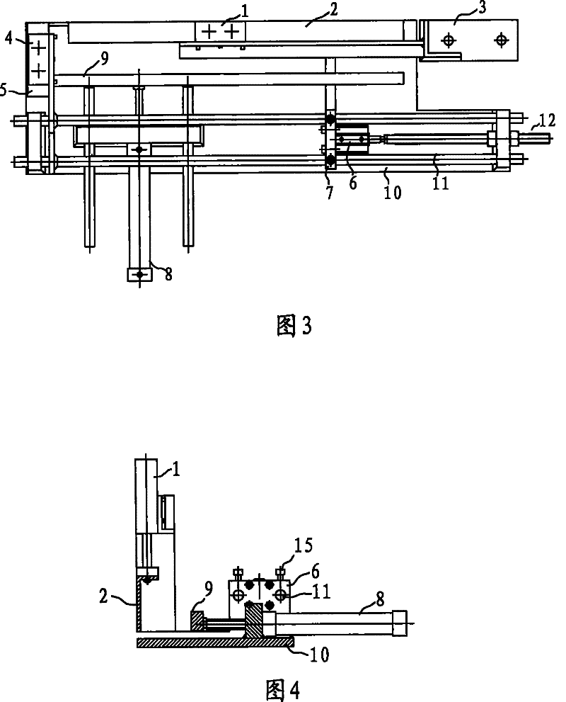
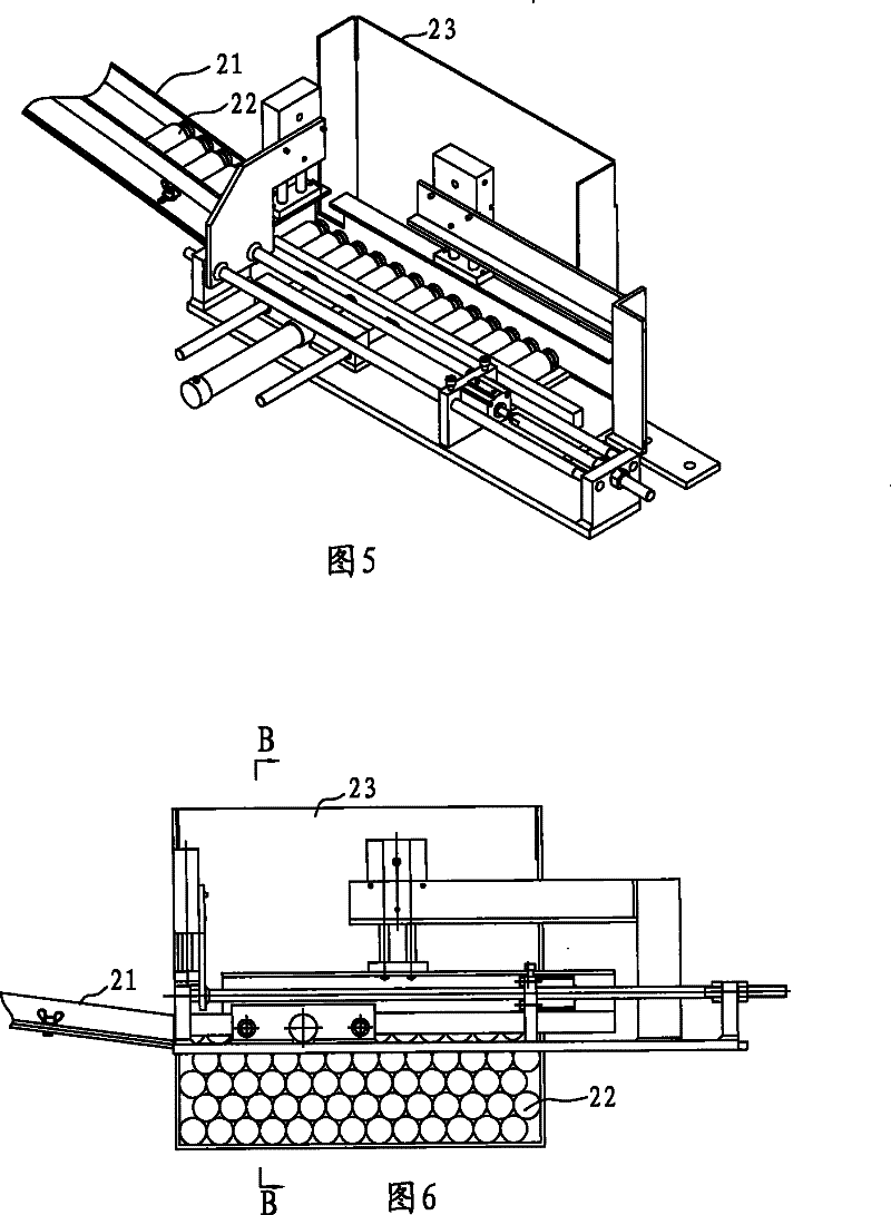
[0031] Example: Reference figure 1 , figure 2 , image 3 and Figure 4 As shown, the bottle pushing device in this embodiment includes a base 10, a front baffle 2, a front cylinder 1, a bottle pushing plate 9, a bottle pushing cylinder 8, a left baffle 5, a left cylinder 4, a right baffle 7 and right cylinder block 6.

[0032] The base 10 is used to carry the glass bottle 22, the front cylinder 1 is used to drive the front baffle 2 to move up and down, the front cylinder 1 is arranged on the front support 3, the front support 3 is L-shaped, and it includes a vertical support part 3b And the horizontal part 3a of the front cylinder block 1 is installed.

[0033] The bottle push plate 9 and the front baffle 2 are arranged at intervals, the bottle push cylinder 8 is used to drive the bottle push plate 9 to move back and forth, the left cylinder 4 is used to drive the left baffle 5 to move up and down, and the left cylinder 4 is arranged on the left bracket 31, and the left ...


PUM


Abstract

The invention relates to a bottle pushing device, which is characterized in that the bottle pushing device comprises a base for bearing a glass bottle, a front baffle plate, a front cylinder body which is used for driving the front baffle plate to lift and is arranged on a front bracket, a bottle pushing plate arranged at interval with the front baffle plate, a bottle pushing cylinder body for driving the bottle pushing plate to move back and forth, a left baffle plate, a left cylinder body which is used for driving the left baffle plate to lift and is arranged on a left bracket, and a right baffle plate arranged at interval with the left baffle plate. Compared with the prior art, the bottle pushing device has the advantages that the bottle pushing device has simple structure, and deft operation, and greatly improves boxing speed of the glass bottle.

Description

technical field [0001] The invention relates to a bottle pushing device, in particular to a bottle pushing device used when glass bottles are packed into packaging boxes. Background technique [0002] In order to put the glass bottles into the packaging box, the general factory adopts manual operation, which results in low work efficiency and poor automation, which affects the speed of products being put on the market. Therefore, a bottle pushing device is needed, which can automatically complete the boxing work. [0003] The existing bottle pushing device can only perform some simple actions, and can push the vertical glass bottle in the working surface, but cannot perform some more complicated or special actions. Common glass bottles are generally cylindrical. When packing, in order to reduce the packing space, the arrangement is more compact and easy to transport. Usually, after packing, the glass bottles in two adjacent rows are staggered by half the diameter of the bott...

Claims


Application Information

Patent Timeline
Patent Type & Authority Patents(China)
IPC IPC(8): B65B21/08
Inventor 曹波
Owner 宁波正力药品包装有限公司
Learn More