Vehicle control device

A technology for a control device and a vehicle, applied in the direction of controlling drive, railway vehicles, vehicle components, etc., can solve the problems of difficult installation or disassembly of the built-in equipment unit 33, time-consuming, difficult installation, disassembly, maintenance and inspection, etc., to simplify installation. and disassembly operations, maintaining device performance, and simplifying the effect of wiring paths

Active Publication Date: 2009-06-03
MITSUBISHI ELECTRIC CORP
View PDF3 Cites 9 Cited by
  • Summary
  • Abstract
  • Description
  • Claims
  • Application Information

AI Technical Summary

Problems solved by technology

However, in the technology of this patent document 3, there is also the following problem, that is, when installing or removing the built-in equipment unit 33, it must be operated not only from one side, but also from the other side, so that it is difficult to install, remove, Repairs and inspections, especially in emergency repairs, are labor-intensive
In addition, since the power line 37 is arranged on one side and the signal line 39 is arranged on the other side, the installation or removal of the built-in equipment unit 33 is performed from the bottom surface of the housing with poor operability, so that it is difficult to install the built-in equipment unit 33. or disassembly operation problems

Method used


Image

  • Vehicle control device
  • Vehicle control device
  • Vehicle control device

Examples


Embodiment approach 1

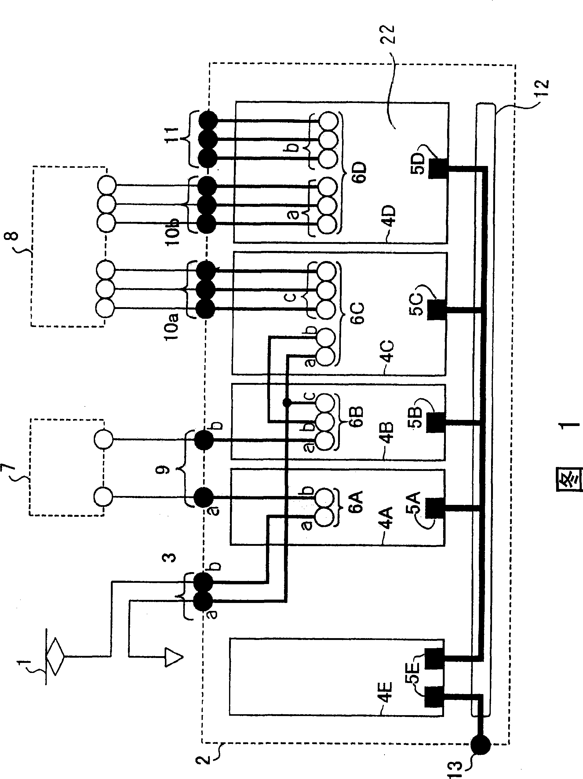
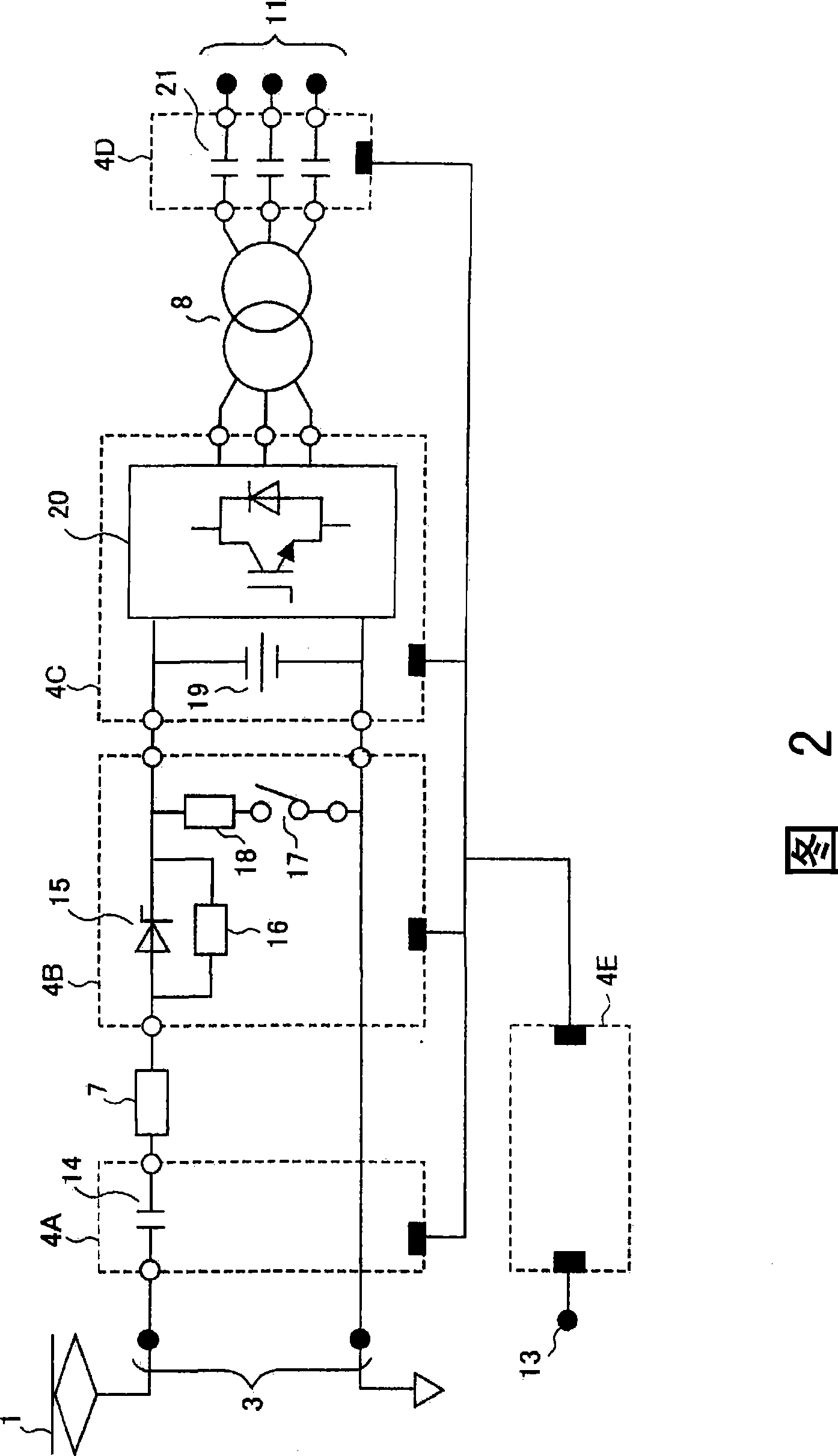
[0056] Embodiment 1 will be described using FIGS. 5 to 6 . FIG. 5 is a block diagram showing a vehicle control device according to Embodiment 1. FIG. In Figures 1 to 2 of the basic technology, the loads are mainly circuit configurations for vehicle lighting and air conditioners, but in Figures 5 to 6, the loads are mainly for vehicle drive motors Circuit structure (VVVF). The figure also shows the division of several functional modules. In FIG. 5 , 1 is an overhead wire, 2 is a vehicle control device main body, and is connected to the overhead wire 1 (the overhead wire side and the ground side) through the input terminal group 3 . 4K, 4L, 4M, 4N, and 4E are functional modules, and all functional modules 4K, 4L, 4M, 4N, and 4E have the first interface area 5K, 5L, 5M, 5N, and 5E in which signal line terminal groups are concentrated. , the functional modules 4K, 4L, 4M, and 4N other than the functional module 4E include second interface areas 6K, 6L, 6M, and 6N in which group...

Embodiment approach 2

[0067] Figure 7 It is a block diagram showing the vehicle control device according to the second embodiment. In addition, in each figure, the same code|symbol represents the same or a corresponding part, and the description is abbreviate|omitted. The same is true for the following. Figure 7 5 shows a structure in which the switching circuit functional module 4K housed in the vehicle control device case in FIG. 5 is separated from the device main body. Figure 7 Among them, 52 is the same switch circuit as the functional module 4K. 53 is a signal line, connected with the functional module 4E. 54 is a terminal group.

[0068] In the case of Embodiment 2, the functional module 4L of the monitoring circuit is connected to the overhead line 1, the reactor 7, the switch circuit 52, the functional module 4N of the overvoltage protection circuit, and the functional module 4M of the inverter, and plays a role in connection. In addition, it also plays various monitoring functions...

Embodiment approach 3

[0074] FIG. 9 is a block diagram showing a vehicle control device according to Embodiment 3. FIG. In particular, changes and additions to the functional modules 4 will be described. Here, in the case of changing the functional module 4N, the functional module 4P (overvoltage protection circuit) is mentioned. This functional module 4P controls the energy consumed by the braking resistor by the switching element and has the function of suppressing the overvoltage of the switching circuit 39. . In addition, as an additional functional module, a functional module 4Q (CCOS = control circuit cut out switch) having a switch function of cutting off a vehicle side circuit and a control circuit, and a functional module 4Q having a function of managing train information and issuing commands to various devices on the vehicle are mentioned. Functional function module 4R (train information management system). In addition, 50 is a braking resistor, and 51 is its connection terminal group. ...


PUM


Abstract

The present invention provides a box-shaped vehicle control device provided under the floor or on the roof of a vehicle to supply electric power to equipment of the vehicle. The vehicle control device is made up of function modules (4) each having an interface surface (22) on one side where a first interface region (5) in which a signal-wire terminal is placed and a second interface region (6) in which an electric-power-wire terminal is placed are separated. The interface surfaces (22) are placed on one end side with the first interface region (5) as a common region and on the other end side with the second interface region (6) as a common region. The function modules have monitor circuits, overvoltage prevention circuits, and inverters.

Description

technical field [0001] The present invention relates to a control device for a vehicle, which is installed in a box shape under the vehicle or on the roof of the vehicle, and is used for supplying electric power to vehicle equipment and the like. Background technique [0002] For example, Patent Document 1 and Patent Document 3 disclose equipment installed in a box shape under a vehicle. Also, for example, Patent Document 2 discloses a device installed in a box shape on the roof of a vehicle. [0003] Patent Document 1: Japanese Patent Application Laid-Open No. 2001-258263 ( image 3 ) [0004] Patent Document 2: Japanese Patent Laying-Open No. 7-17396 ( image 3 ) [0005] Patent Document 3: Japanese Patent Laid-Open No. 5-199601 (Fig. 1, Fig. 2) [0006] In the prior art of Patent Document 1, although the arrangement of the main components accommodated in the housing is described, there is almost no mention of the relationship between the arrangement of electrically con...

Claims


Application Information

Patent Timeline
Patent Type & Authority Applications(China)
IPC IPC(8): B60L1/04B60L1/16B61C17/12
CPCB60L2200/26B60L15/007B61C17/00B60L1/003Y02T10/64B60L1/04B60L1/16
Inventor 池本稔冈山秀夫北中英俊角田英俊糀芳信上田清信足立泰久杉浦诚
Owner MITSUBISHI ELECTRIC CORP
Why Eureka
Try Eureka