Bipolar scissor ball head structure

A technology of scissor head and scissors, which is applied in the field of medical equipment and can solve problems such as affecting operation and easily blocking sight

Inactive Publication Date: 2021-04-20
杭州桐庐医达器械设备有限公司
View PDF6 Cites 2 Cited by
  • Summary
  • Abstract
  • Description
  • Claims
  • Application Information

AI Technical Summary

Problems solved by technology

The utility model can automatically electrocoagulate hemostasis during the cutting process, improve the operation efficiency, and is convenient and safe to use. However, the bipolar electrocoagulation joint of the utility model is located on the upper side of the scissors seat, which easily blocks the line of sight and affects the operation.

Method used


Image

  • Bipolar scissor ball head structure
  • Bipolar scissor ball head structure
  • Bipolar scissor ball head structure

Examples


Embodiment

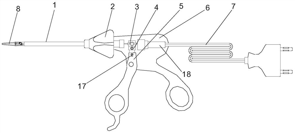
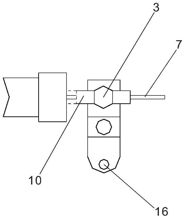
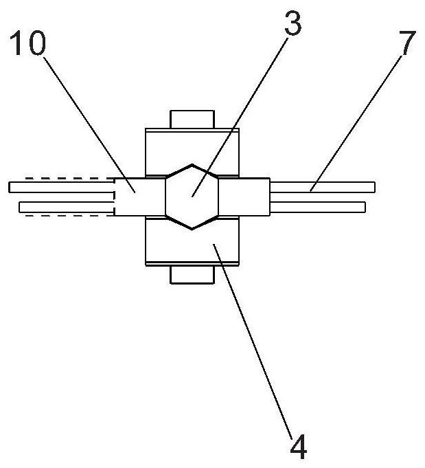
[0021] Such as Figure 1 to Figure 4 As shown, a ball head structure of bipolar scissors is arranged in the bipolar scissors. The bipolar scissors include a pincer rod 1, a runner 2, a front handle 5, a rear handle 6, a wire 7 and a scissors head 8. The scissors head 8 is located at The front end of the clamp rod 1 is fixed on the runner 2, the runner 2 is connected to the rear handle 6, the front handle 5 is hinged on the rear handle 6, the wire 7 is electrically connected to the scissor head 8, and the end of the clamp rod 1 is provided with a nylon The ball head 3 is a flat cylinder, the ball head 3 is installed on a ball seat 4, the ball seat 4 is hinged on the back handle 6 and is connected with the front handle 5 at the same time, and the wire 7 passes through the ball head 3 Enter clamp lever 1. The clamp rod 1 includes a sleeve 9 and a pull tube 10, the sleeve 9 is fixed on the runner 2, the front end of the sleeve 9 is fixed with a scissors head 11, the scissors head...


PUM


Abstract

The invention discloses a bipolar scissors ball head structure. The bipolar scissors ball head structure is arranged in bipolar scissors. The bipolar scissors comprise a forceps rod, a rotating wheel, a front handle, a rear handle, a wire and a scissors head, the scissors head is located at the front end of the forceps rod, the forceps rod is fixed to the rotating wheel, the rotating wheel is connected with the rear handle, the front handle is hinged to the rear handle, the wire is electrically connected with the scissors head, a ball head is arranged at the tail end of the forceps rod, the ball head is installed on a ball seat, the ball seat is hinged to the rear handle and connected with the front handle at the same time, and the wire penetrates through the ball head to enter the forceps rod. The wire penetrates through the ball head, the ball head further supports the wire, the wire can be arranged in the direction of the forceps rod, the wire can be connected into the bipolar scissors right behind the rear handle and roughly corresponds to the position of the forceps rod, the shielding on the sight line and the interference on the operation of the hand can be reduced to the minimum, the wiring path is simplified, and the operation is convenient.

Description

technical field [0001] The invention relates to a medical device, more specifically to a bipolar scissors ball head structure. Background technique [0002] In the process of traditional minimally invasive surgery, a variety of knives and scissors are often used to separate human organs and tissues. After cutting with knives and scissors, special coagulation equipment is used to coagulate blood. This traditional cutting and coagulation operation method , requires step-by-step operation, not only to prepare a variety of instruments, but also prolong the operation time. Bipolar scissors can not only perform normal cutting, but also provide high-frequency electric energy to the body tissue through the two tips, so that the blood vessels or tissues between the two ends of the bipolar scissors can be dehydrated and coagulated, so as to achieve the purpose of hemostasis, and the calorific value is low , and the scope of action is limited to the two ends of the bipolar scissors, t...

Claims


Application Information

Patent Timeline
Patent Type & Authority Applications(China)
IPC IPC(8): A61B18/12A61B18/14
Inventor 朱国锋韩国勇张永金朱国华
Owner 杭州桐庐医达器械设备有限公司
Why Eureka
Try Eureka