Glazing inspection

A glass window and image technology, applied in the direction of measuring devices, material analysis through optical means, instruments, etc., can solve the problems of information loss, low combination response, determining whether there is a defect or whether it meets the pass/fail standard and other complicated problems

Inactive Publication Date: 2009-06-03
PILKINGTON GRP LTD
View PDF0 Cites 16 Cited by
  • Summary
  • Abstract
  • Description
  • Claims
  • Application Information

AI Technical Summary

Problems solved by technology

However, when doing so, the peaks in the darkfield signal combined with the valleys in the brightfield signal can result in a low combined response, as many artifacts that scatter light and produce a darkfield image will absorb light in the brightfield image
Additionally, the dynamic range of the measured signal is compromised and information is lost
Therefore, determining whether a defect exists or meets pass / fail criteria is complex and false rejections may occur
Therefore, such methods are difficult to implement successfully on the production line

Method used


Image

  • Glazing inspection
  • Glazing inspection
  • Glazing inspection

Examples


Embodiment Construction

[0019] In the present invention, it has been recognized that light from two light sources of different wavelengths can be used to generate brightfield and darkfield images of defects in the glazing and can be detected using one image capture device. By successfully combining brightfield and darkfield techniques, shadowed images of glass windows can also be produced using the same light source as that used for brightfield images.

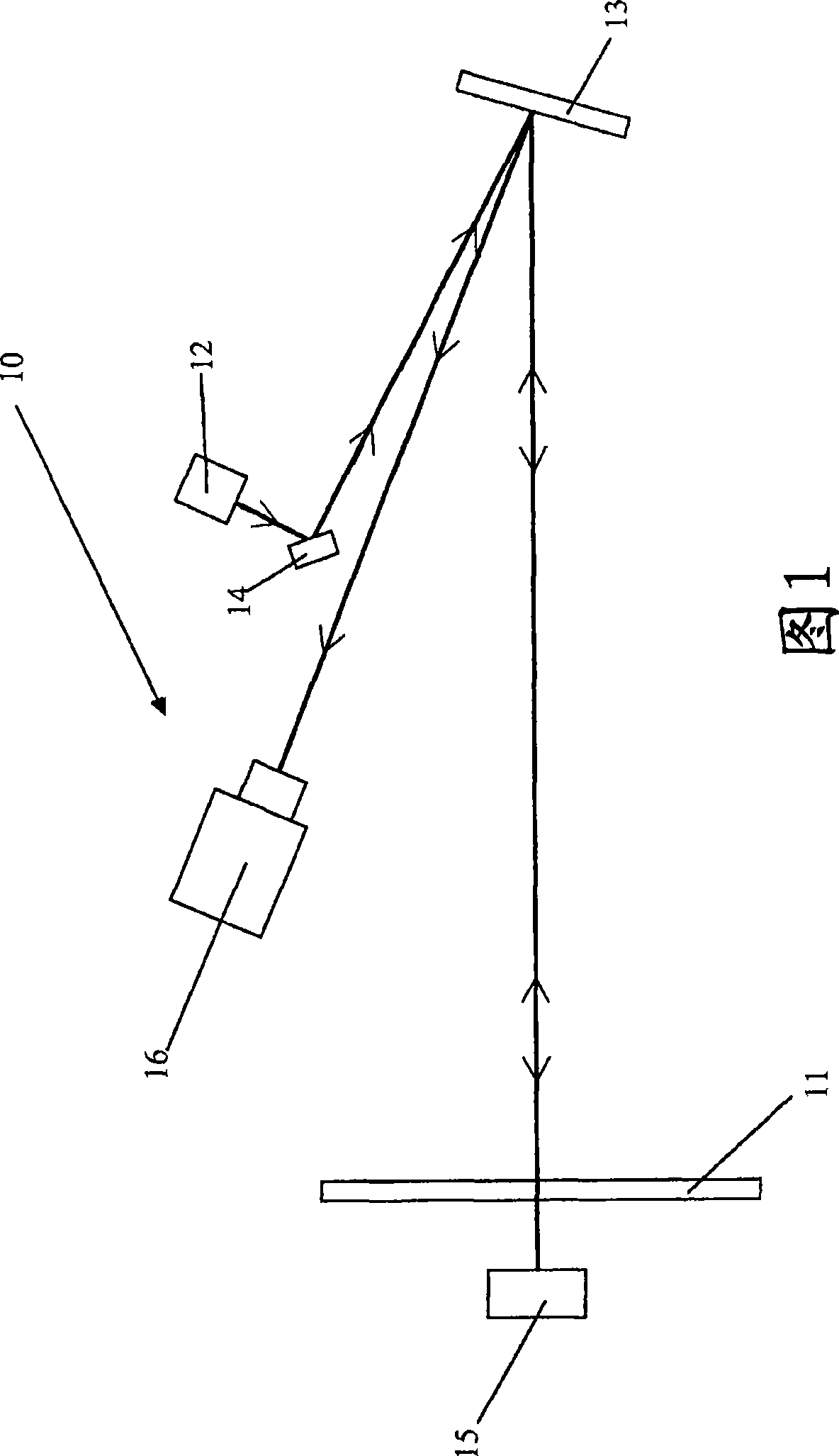
[0020] Figure 1 is an exemplary ray diagram of an optical inspection setup set up for brightfield imaging. An optical inspection apparatus 10 is shown in which a glazing 11 (supported on not shown supports) in position is inspected in transmitted light. The device 10 comprises an LED (Light Emitting Diode) point light source 12 emitting light reflected by a large reflector 13 and incident on a glass window 11 . The light from the LED point light source 12 is directed by the small reflector 14 to the large reflector. The strip spherical mirror 15 is...


PUM


Abstract

The present invention discloses a method of inspecting a glazing for faults. The method comprises illuminating the glazing, with light having a first wavelength, to produce a bright-field image illuminating the glazing, with light having a second wavelength, to produce a dark- field image. The bright-field image and dark-field image are captured using a single image capture device. The bright-field and dark-field images may be focussed onto the image capture device by a common lens. In addition, a shadowgraph image may be recorded simultaneously. The inspection method provides an improved fault detection system for glazings, such as automotive glazings.

Description

technical field [0001] This invention relates to the inspection of glazing and, in particular, to the inspection of glazing for deformed and non-deformed faults. Background technique [0002] During production, glass for automotive glazing is inspected for various defects that may affect the optical quality of the finished glazing product. For example, glass may have imperfections due to handling such as edge imperfections, brillantatura, and shiners from the cutting and grinding processes used to cut the glass to size. Alternatively, flaws may arise from deformation, thickness and curvature changes resulting from the firing and bending processes used to shape the glass. For example, secondary images can be seen when viewing objects through shaped glass. This is the case for single and multiple glazing windows. [0003] Flaws can also be caused within the glass body by the glass manufacturing process, or on the glass surface by handling during or after manufacture. For e...

Claims


Application Information

Patent Timeline
Patent Type & Authority Applications(China)
IPC IPC(8): G01N21/958
CPCG01N21/958G01N2021/9586G01N2021/8825
Inventor B·R·希尔
Owner PILKINGTON GRP LTD
Why Eureka
Try Eureka