Display

a technology of display and display panel, applied in the field of displays, can solve the problems of image degradation, distracting image mixing, and more noticeable problems, and achieve the effect of increasing luminance and reducing image mixing

Inactive Publication Date: 2007-01-18
SHARP KK
View PDF10 Cites 130 Cited by
  • Summary
  • Abstract
  • Description
  • Claims
  • Application Information

AI Technical Summary

Benefits of technology

[0016] A display of the second aspect can create the impression of 2-D resolution by time multiplexing but without introducing nominally full area black periods between frame refresh to each user (in other words, it uses time multiplexing of a spatially multiplexed display rather than full frame temporal multiplexing). A user can perceive the full 2D screen resolution without coarse image flickering problems associated with the conventional image-black-image-black cycle discussed previously in full frame temporal multiplexed schemes. Further the image quality is improved (there is a reduced “prison-bar” effect) compared to a fixed dual-view display with parallax barriers.
[0023] A display of this aspect of the invention is operable either in a full-resolution 2D mode without time multiplexing or in a multiple view directional display mode in which full-resolution is achieved by time multiplexing. The image quality of the 2D mode is improved due to effectively eliminated reduction of flickering since no time multiplexing is used. Further the image quality of the multiple view directional display mode is improved owing to enhanced resolution and a reduced “prison-bar” effect.
[0032] This aspect of the invention may be embodied using, for example, a liquid crystal SLM with a colour filter array. The regions of the backlight co-operate with the colour filters of the liquid crystal SLM to form a multiple view directional display. Light is emitted by the backlight only in the correct location for a multiple view directional display, and this increases luminance and decreases image mixing.

Problems solved by technology

When such a display is used as an autostereoscopic 3D display, this disadvantage is partially compensated because one viewer sees all of the pictures elements (pixels) of the LCD 2, with one eye seeing half of the pixels and the other eye seeing the remaining half of the pixels.
This may create image degradation problems through colour artefacts and anti-aliasing issues.
However in the case of a dual-view display, scatter from the plastic waveguide and corresponding plastic structure can lead to very distracting image mixing.
For dual-view this problem is more noticeable since typically two totally independent images will be displayed, which is not the case for autostereoscopic displays, especially those displaying images with small disparities.
This leads to reduction in image quality in one of the modes.
Further, this system relies on liquid crystal lenses and these are often relatively scattering.
This multi-view configuration degrades the users head freedom compared to a configuration providing nominally only 2 independent primary zones over the full view zone of the display.
This reduction in head freedom is particularly problematic for an automotive environment where full head freedom for a driver or passenger is required.
Finally, in an automotive environment, the images from the display have to be imaged at reasonably high angles and image degradation or image mixing may result from the lens aberrations related to such high angle imaging.

Method used


Image

  • Display
  • Display
  • Display

Examples


Embodiment Construction

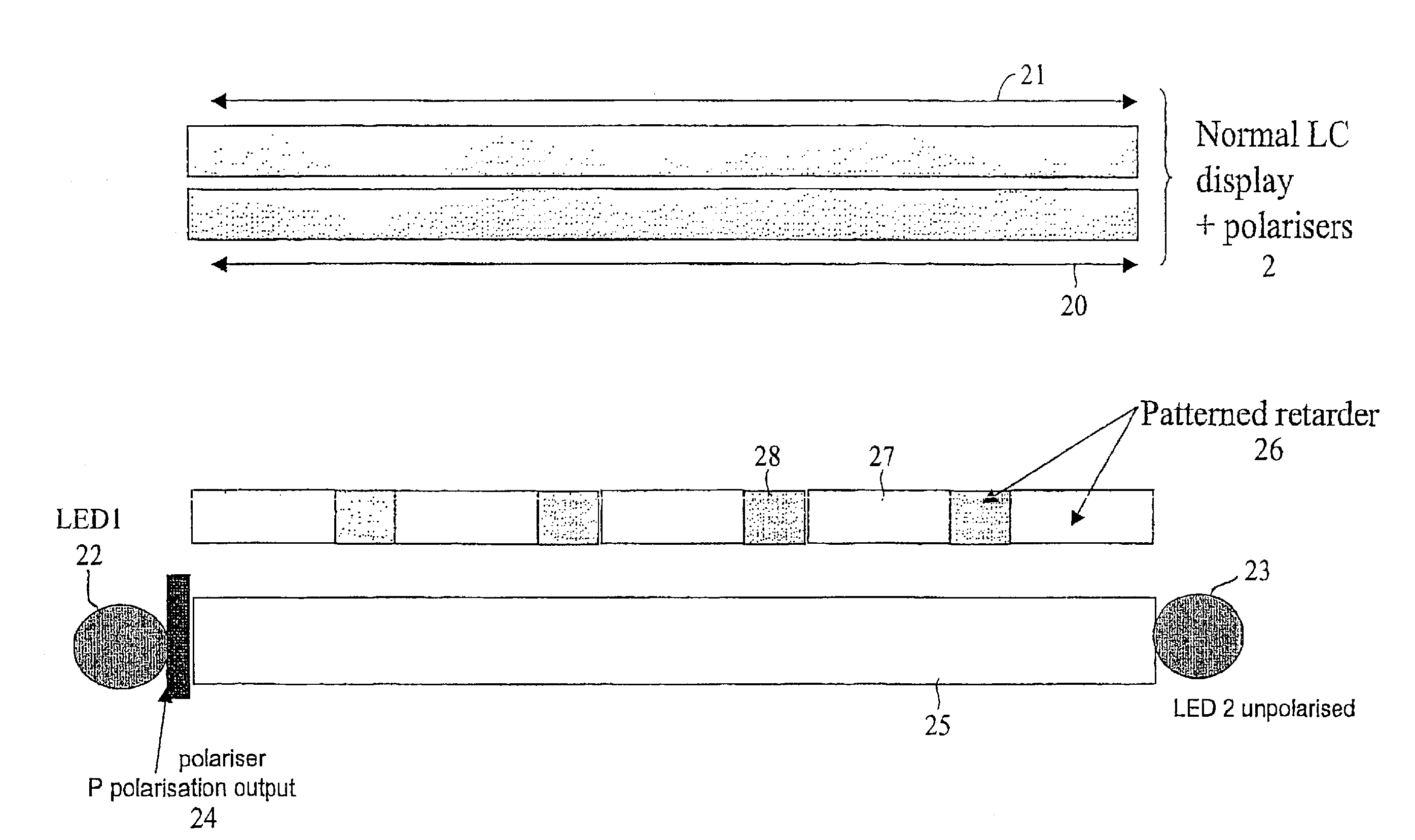
[0068] The display shown in FIG. 5 comprises a conventional LCD 2 including input and output polarisers 20 and 21. The LCD 2 is of the transmissive or trans-reflective type and cooperates with a backlight comprising light sources 22 and 23, for example comprising light emitting diodes (LEDs), a polariser 24 which, in this example, transmits P polarised light, a light guide 25, and a patterned retarder 26. In order to prevent or reduce depolarisation of the polarised light supplied by the light source 22 and the polariser 24 within the light guide 25, the light guide may contain nanoparticle elements for reducing residual birefringence as described in Proceedings of International Displays Workshop 2004, paper LCT4-3 “Nanoparticle Zero Birefringence Backlight Waveguide”.

[0069] The patterned retarder 26 comprises a half wave plate having regions such as 27, whose optic axis is oriented so as not to have an effect on P polarised light, and regions 28, whose optic axis is oriented so as...


PUM


Abstract

A display is provided having a multiple view mode of operation and a wide angle single view mode. The display comprises a transmissive spatial light modulator which displays spatially multiplexed images in the multiple view mode and a single image with full resolution in the single view mode. The modulator has an input polariser which passes light of a first polarisation. A backlight has a light output surface with alternating first and second regions of parallel strip shape. The backlight is electronically switchable between the multiple view and single view modes. In the multiple view mode, only the first regions emit light containing the first polarisation. In the single view mode, both regions emit light containing the first polarisation.

Description

[0001] This Nonprovisional application claims priority under 35 U.S.C. § 119(a) on Patent Application No. 0514278.1 filed in U.K. on Jul. 13, 2005, the entire contents of which are hereby incorporated by reference. FIELD OF THE INVENTION [0002] The present invention relates to displays. For example, such displays may have at least one mode in which images of independently selectable content are visible only in respective different viewing regions. An example of an application of such a display is in the dashboard of a vehicle for viewing by a driver and, when present, one or more passengers. BACKGROUND OF THE INVENTION [0003] Although such displays may be capable of displaying any number of views visible in a corresponding or different number of viewing regions, many applications require only two views. Displays of this type are referred to as dual view displays. FIG. 1 of the accompanying drawings illustrates the operation of such a dual view display in a vehicle dashboard. For exa...

Claims


Application Information

Patent Timeline
Patent Type & Authority Applications(United States)
IPC IPC(8): G09G3/34G02B30/28
CPCB82Y20/00G02B27/06G02B27/2214G02B27/26G02F1/133615H04N13/045G02F1/13363G02F1/13471G02F2001/133633G02F2202/36G02F2413/09G02F1/133617H04N13/32H04N13/354G02B30/25G02F1/133633G02F1/133631G02B30/28G02B30/27
Inventor BOURHILL, GRANT
Owner SHARP KK
Why Eureka
Try Eureka