Eureka AIR delivers breakthrough ideas for toughest innovation challenges, trusted by R&D personnel around the world.

Generation of aerial images

a technology of aerial images and images, applied in the field of aerial image generation, can solve the problems of difficult operations, poor overview, and few clues, and achieve the effects of improving accuracy, reducing labor intensity, and improving accuracy

Active Publication Date: 2011-04-21
IMINT IMAGE INTELLIGENCE AB
View PDF11 Cites 136 Cited by
  • Summary
  • Abstract
  • Description
  • Claims
  • Application Information

AI Technical Summary

Benefits of technology

[0016]It is a further advantage of the invention that the high quality aerial image mosaics can be provided in real time without any additional motion control system such as GPS or the like, gyroscopes or accelerometers.
[0017]An aerial image system according to the invention is more robust, cheaper, and lighter than conventional systems, which makes it suitable for unmanned aerial vehicles (UAV). Quality images and video sequences can be produced using an inexpensive UAV and off the shelf cameras.
[0018]Embodiments of the invention are defined in the dependent claims. Other objects, advantages and novel features of the invention will become apparent from the following

Problems solved by technology

Furthermore, visual inspection of only one isolated image frame gives few clues to the orientation and location of the area where the image is taken and a poor overview.
The matching and stitching of images are challenging operations, not least since the alignment of overlapping images to form the mosaic are computationally intensive.
The motion control can be improved by using GPS signals or the like to determine the position and the altitude of the acquisition system, which also significantly reduces the computing speed of the matching operation.
However, to find two neighbouring images in cross strip matching as described in the above it may not enough to use the GPS position.
Aerial image systems are limited by the computational power and only a limited number of images can be matched together in a certain time period.
However, in opposition to the suggested improvements of the system the UAV do not allow any additional payload, rather the aerial image system should be decreased in size, weight, complexity and cost.

Method used


Image

  • Generation of aerial images
  • Generation of aerial images
  • Generation of aerial images

Examples


Embodiment Construction

[0038]Different methods for generating an aerial image from a plurality of images are known. Usually one image is matched to another by finding a feature in one image and finding the same feature in the other image and then aligning the images to form a larger image. The features are commonly defined by feature points. In photogrammetry one generally relies on high precision metric cameras and the images are orthonormal (i.e. the image nadir and image centre are aligned). Also information about the 3D motion is always known through telemetry data. In panorama image generation there is no (or negligible) translation and only rotation along one or two axis. Both in the photogrammetry case and the panorama image case there are often only one, or maybe two, general degrees of freedom (DOF) and all other motion parameters can be regarded as small. Conventional methods rely on that the motion of the camera and the scene to be imaged is limited and predictable or else the computing power h...


PUM


Abstract

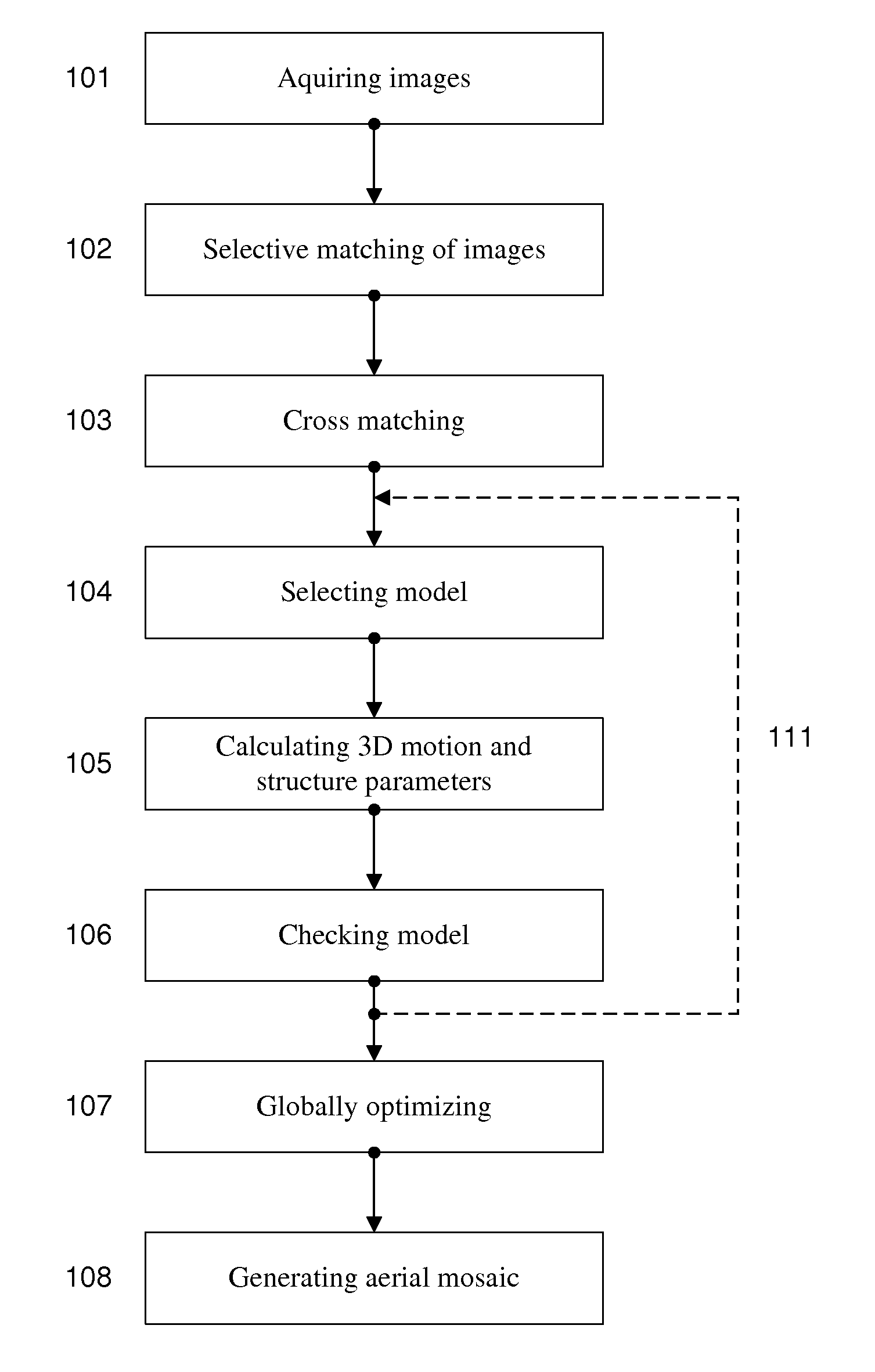
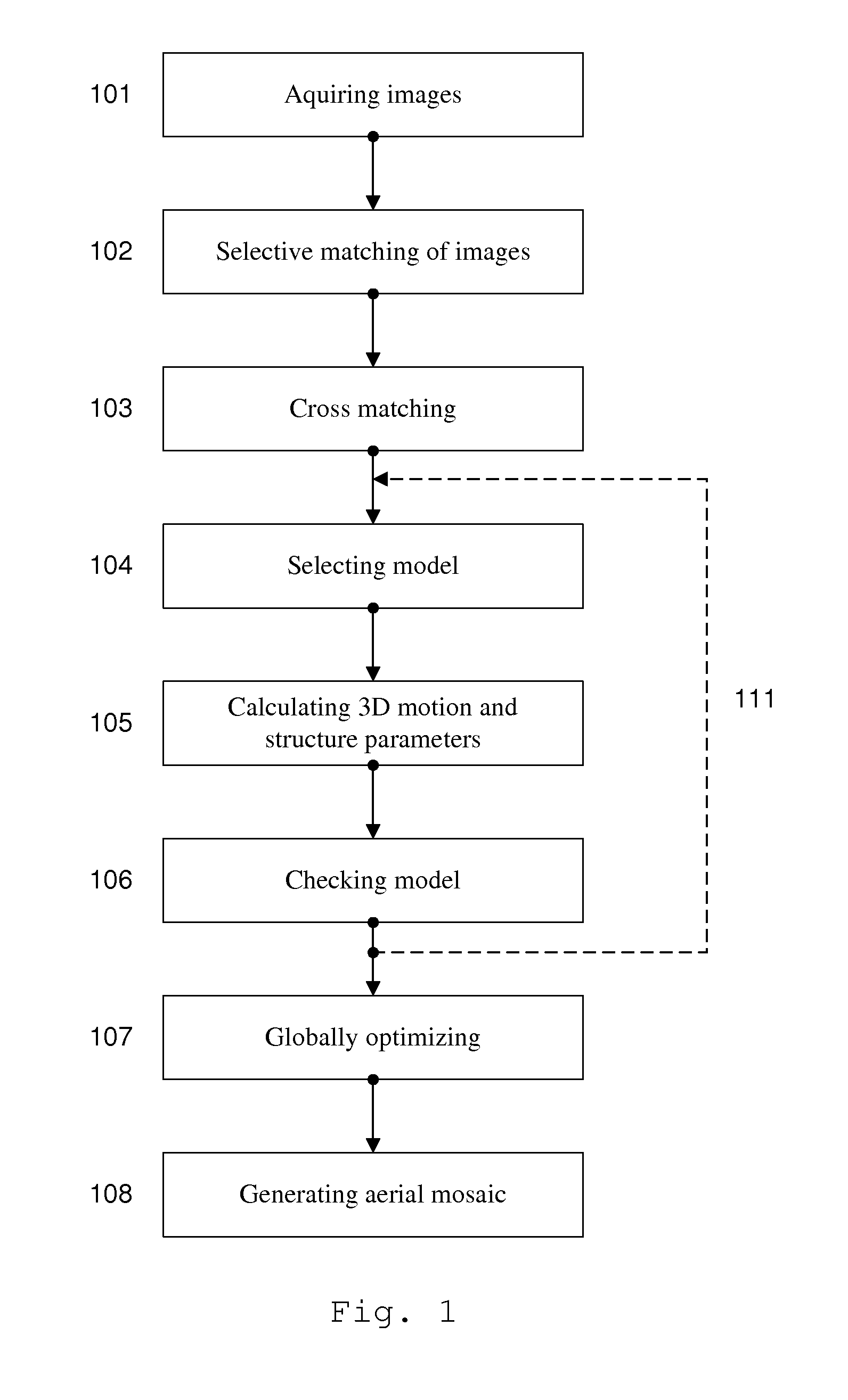
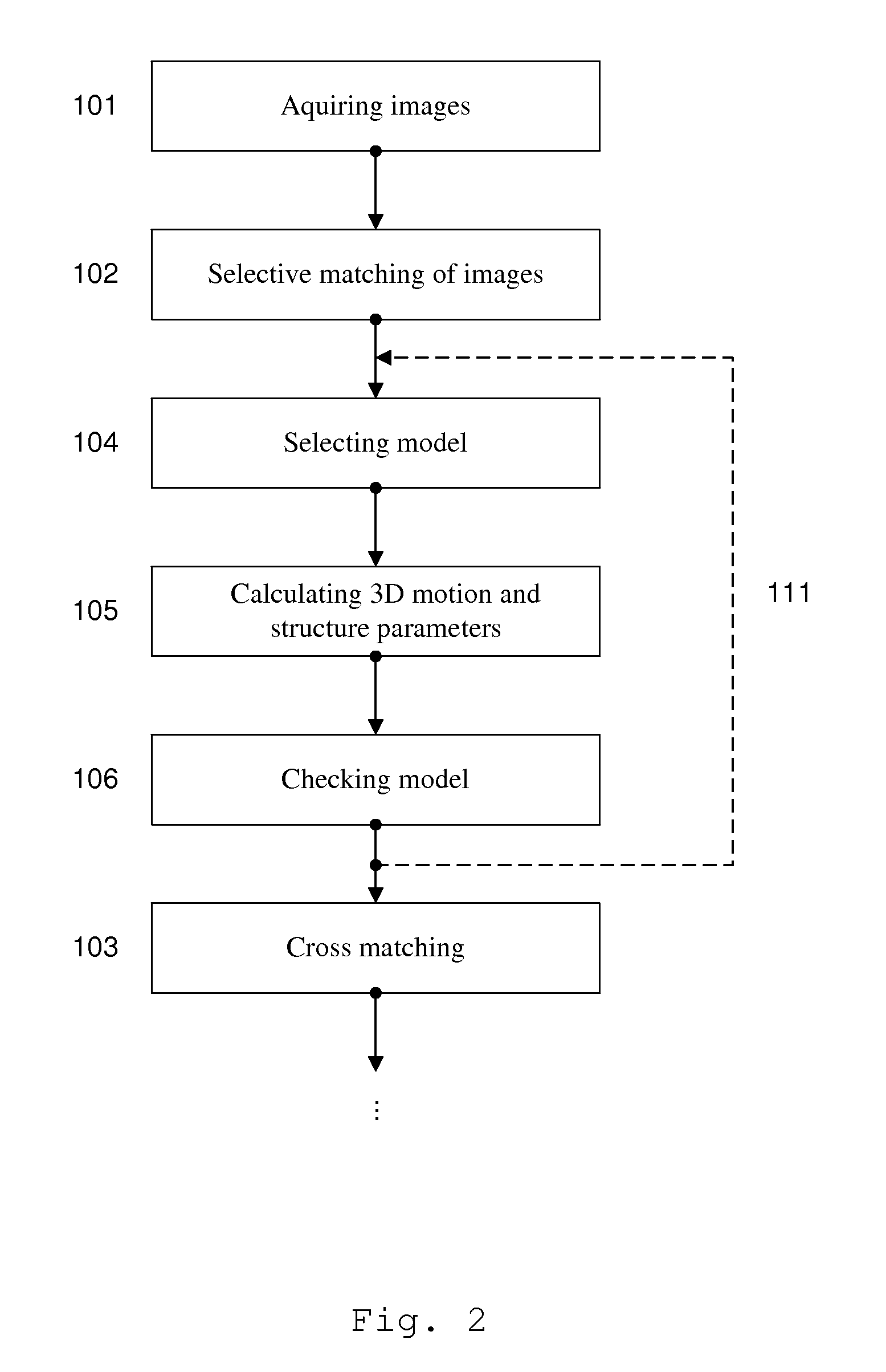
The method according to the invention gene rates an aerial image mosaic viewing a larger area than a single image from a camera can provide using a combination of computer vision and photogrammetry. The aerial image mosaic is based on a set of images acquired from a camera. Selective matching and cross matching of consecutive and non-consecutive images, respectively, are performed and three dimensional motion and structure parameters are calculated and implemented on the model to check if the model is stable. Thereafter the parameters are globally optimised and based on these optimised parameters the serial image mosaic is generated. The set of images may be limited by removing old image data as new images are acquired. The method makes it is possible to establish images in near real time using a system of low complexity and small size, and using only image information.

Description

TECHNICAL FIELD OF THE INVENTION[0001]The present invention relates to generation of aerial images, and in particular generation of aerial image mosaics.BACKGROUND OF THE INVENTION[0002]In aerial imaging the surface of an object is typically imaged using an aerial imaging system freestanding from the object. For example an aerial image can be acquired by aerial photography using a camera. More specifically, aerial imaging can be used to provide an image of the ground using an elevated camera. Aerial imaging is useful in cartography, archaeology, environmental studies, tactical and strategic use by civilian and military intelligence, etc. Commonly an image acquisition system of the aerial imaging system is mounted in a flying vehicle of some kind. Examples of such are satellites orbiting the earth, and helicopters or aircrafts flying over the area to be imaged. Unmanned aerial vehicles (UAV) are also becoming more popular as they become more capable, have an endurance that outperform...

Claims


Application Information

Patent Timeline
IPC IPC(8): H04N7/18
CPCH04N7/18G01C11/025
Inventor KLOMP, HARALDSANDSTROM, JAKOB
Owner IMINT IMAGE INTELLIGENCE AB
Why Eureka
Eureka Blog
Learn More