
fm transceiver

A transceiver and receiver technology, applied in electrical components, radio transmission systems, transmission systems, etc., can solve the problems of complex structure, difficult integration, and difficult clock processing of FM signal transceivers

Inactive Publication Date: 2012-02-15
RDA TECH
View PDF0 Cites 0 Cited by
  • Summary
  • Abstract
  • Description
  • Claims
  • Application Information

AI Technical Summary

Problems solved by technology

[0002] The structure of the existing FM signal transceiver is complex, and the FM reception and FM transmission are respectively implemented by independent chips, which are difficult to integrate. Even if they are integrated together, the multiplexing rate of the modules is very low.
[0003] FM transmission is mainly based on the analog transmission structure of direct up-conversion, and the multiplexing rate of the transceiver clock and modules is low. At the same time, the clock processing required by the internal modules is very difficult. In the transmission mode, an external high-frequency reference clock (instead of 32.768 kHz reference clock commonly used for FM reception)

Method used


Image

  • fm transceiver
  • fm transceiver
  • fm transceiver

Examples


Embodiment Construction

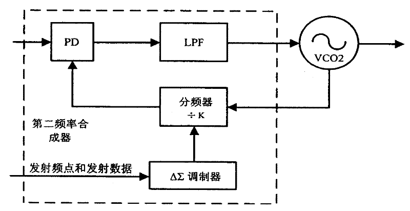
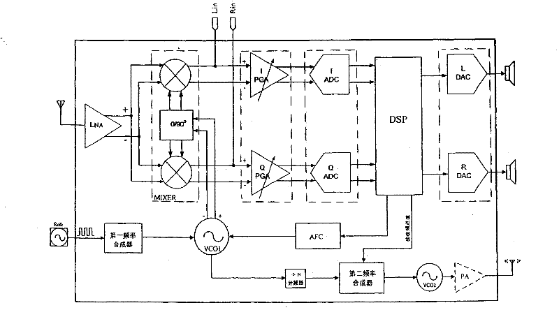
[0023] see figure 1 As shown, the FM transceiver of the present invention includes an FM receiver and a dual frequency synthesizer.

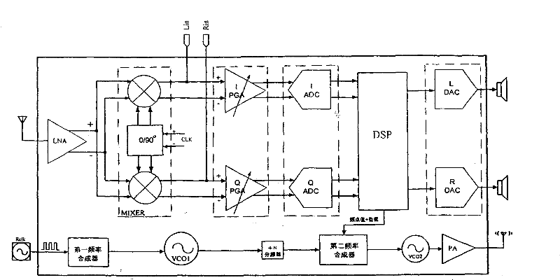
[0024] combine figure 2 As shown, the described FM receiver has the same circuit structure as the existing receiver, and adopts low intermediate frequency digital reception and digital demodulation. Specifically include:

[0025] The low noise amplifier LNA amplifies the FM signal received by the antenna and sends it to the mixer MIXER.

[0026] The mixer MIXER down-converts the signal to a preset low frequency point, and converts it into two differential signals of I and Q, which are sent to the respective adjustable gain amplifiers IPGA and QPGA.

[0027] The adjustable gain amplifiers PGAI and PGAQ adjust the amplitude of the received differential signal and filter out-of-band noise, and then transmit the signal to the respective analog-to-digital converters IADC and QADC.

[0028] The analog-to-digital converters IADC and QADC convert t...


PUM


Abstract

The invention discloses an FM transceiver, which includes an FM receiver and a double frequency synthesizer; the double frequency synthesizer includes a first frequency synthesizer and a second frequency synthesizer, and when receiving a signal, the first frequency synthesizer and the first voltage controlled oscillator Provide the high-frequency clock of the local oscillator for the mixer; the second frequency synthesizer and the second voltage-controlled oscillator provide clocks for other modules in the FM receiver; when transmitting signals, the second frequency synthesizer is responsible for loading the transmit frequency point and data , the first frequency synthesizer and the first voltage-controlled oscillator provide clocks for other modules in the FM receiver; when transmitting signals, the digital signal processor directly digitally modulates the transmitted data to the second frequency synthesizer, and then the The power amplifier amplifies and sends out. The invention can integrate the FM receiving and transmitting chips together, and the multiplexing rate of the modules inside the transceiver is high. The invention is suitable for FM / AM demodulation and modulation receivers.

Description

technical field [0001] The present invention relates to a radio frequency signal transceiver, in particular to an FM (Frequency Modulate, frequency modulation signal) transceiver. Background technique [0002] The structure of the existing FM signal transceiver is complex, and the FM reception and FM transmission are implemented by independent chips, which are difficult to integrate. Even if they are integrated together, the multiplexing rate of the modules is very low. [0003] FM transmission is mainly based on the analog transmission structure of direct up-conversion, and the multiplexing rate of the transceiver clock and modules is low. At the same time, the clock processing required by the internal modules is very difficult. In the transmission mode, an external high-frequency reference clock (instead of FM reception commonly used 32.768 kHz reference clock). Contents of the invention [0004] The technical problem to be solved by the present invention is to provide ...

Claims


Application Information

Patent Timeline
Patent Type & Authority Patents(China)
IPC IPC(8): H04B1/40H04B7/00
Inventor 赵春魏述然张亮
Owner RDA TECH
Learn More