Zoom lens, digital camera, and portable information device

A zoom lens and lens technology, applied in the direction of optical components, optics, instruments, etc., can solve the problem of not being able to fix the lens, and achieve the effect of excellent dust resistance and large zoom ratio

Inactive Publication Date: 2009-06-10
SHARP KK
View PDF3 Cites 6 Cited by
  • Summary
  • Abstract
  • Description
  • Claims
  • Application Information

AI Technical Summary

Problems solved by technology

[0007] However, in this configuration, in order to suppress the shift of the focus position during magnification change, it is necessary to drive the first group lens in addition to the third group lens. fixed

Method used


Image

  • Zoom lens, digital camera, and portable information device
  • Zoom lens, digital camera, and portable information device
  • Zoom lens, digital camera, and portable information device

Examples


Embodiment approach 1

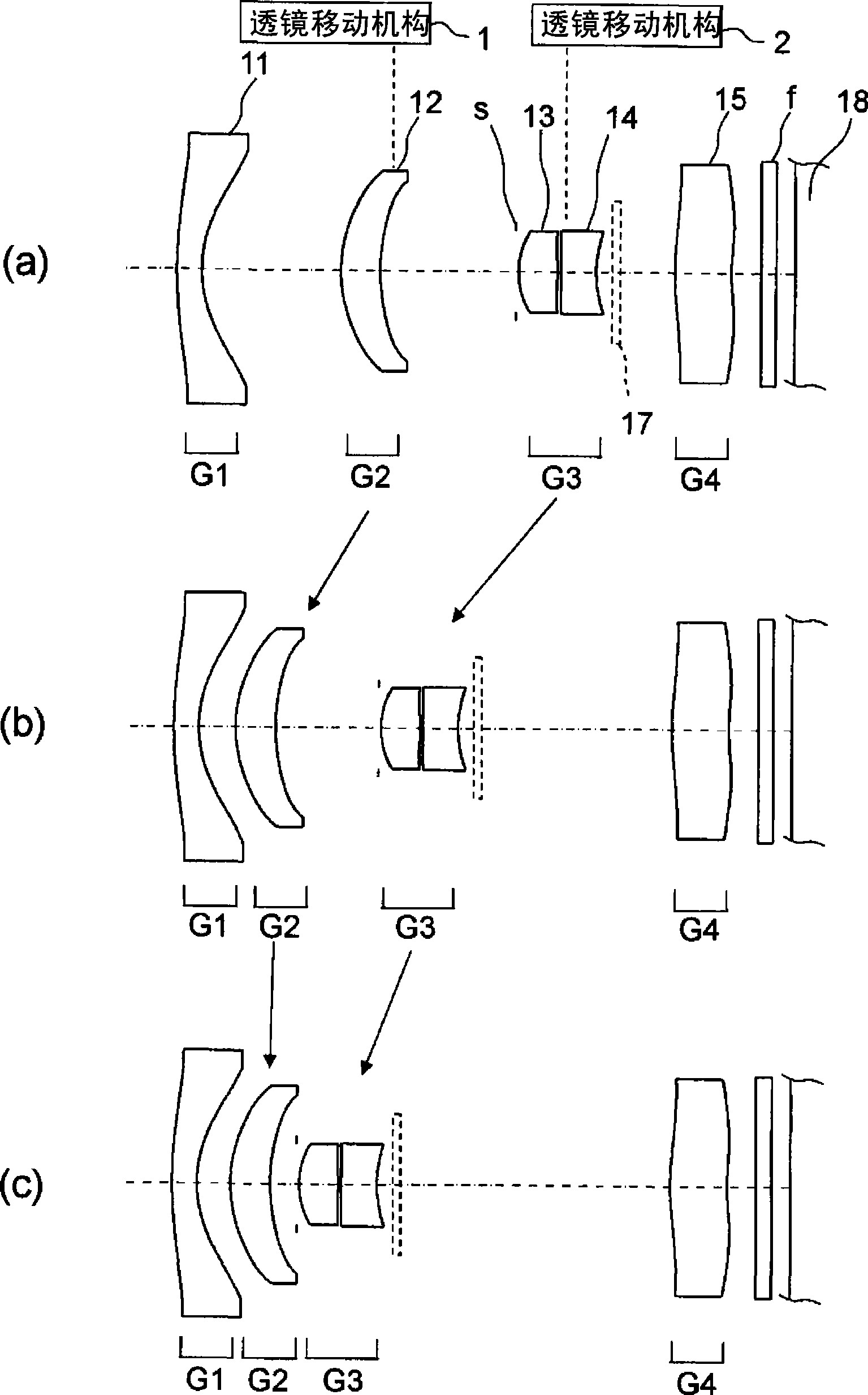
[0066] figure 1 is a cross-sectional view showing the composition of the zoom lens according to Embodiment 1 of the present invention, and in each cross-sectional view, figure 1 (a), figure 1 (b) and figure 1 (c) represent the zoom positions of the wide-angle end, intermediate focal length, and telephoto end, respectively. figure 1 The left side of is the object side, and the right side is the image plane side. The arrows in the figure indicate the movement of the lens during zooming.

[0067] like figure 1 As shown, the zoom lens of Embodiment 1 includes: a first group lens G1 with negative refractive power; a second group lens G2 with positive refractive power; a third group lens G3 with positive refractive power; and a negative refractive power The fourth group lens G4, the first group lens G1, the second group lens G2, the third group lens G3 and the fourth group lens G4 are zoom lenses arranged in order from the object side to the image plane side. This zoom lens fi...

Embodiment approach 2

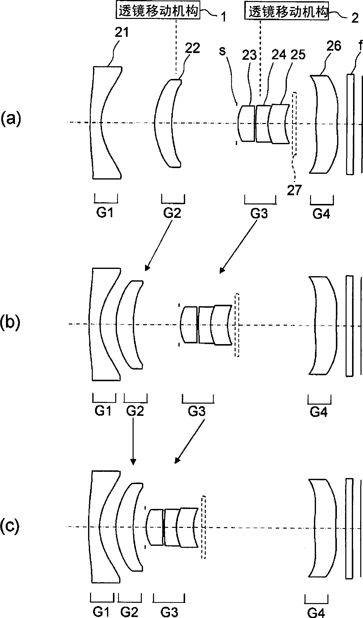
[0097] figure 2 It is a cross-sectional view showing the composition of the zoom lens according to Embodiment 2 of the present invention. In each cross-sectional view, figure 2 (a), figure 2 (b) and figure 2 (c) represent the zoom positions of the wide-angle end, intermediate focal length, and telephoto end, respectively. figure 2 The left side of is the object side, and the right side is the image plane side. The arrows in the figure indicate the movement of the lens during zooming.

[0098] like figure 2 As shown, the zoom lens of Embodiment 2 includes: the first group lens G1 with negative refractive power; the second group lens G2 with positive refractive power; the third group lens G3 with positive refractive power; and the third group lens G3 with negative refractive power The fourth group lens G4, the first group lens G1, the second group lens G2, the third group lens G3 and the fourth group lens G4 are zoom lenses arranged in order from the object side to th...

Embodiment approach 3

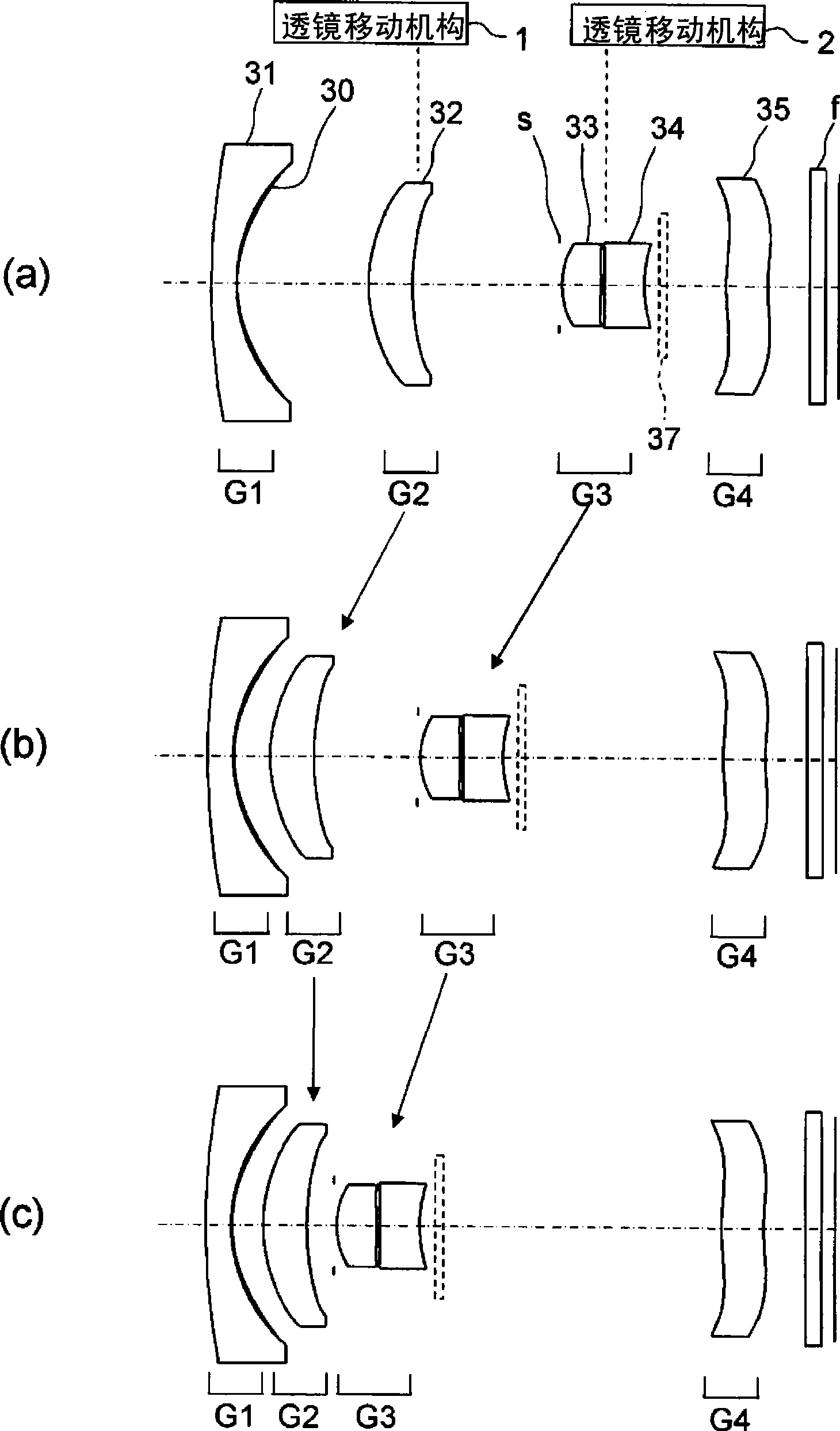
[0123] image 3 It is a cross-sectional view showing the composition of the zoom lens according to Embodiment 3 of the present invention. In each cross-sectional view, image 3 (a), image 3 (b) and image 3 (c) represent the zoom positions of the wide-angle end, intermediate focal length, and telephoto end, respectively. image 3 The left side of is the object side, and the right side is the image plane side. The arrows in the figure indicate the movement of the lens during zooming.

[0124] like image 3 As shown, the zoom lens of Embodiment 3 includes: the first group lens G1 with negative refractive power; the second group lens G2 with positive refractive power; the third group lens G3 with positive refractive power; and the third group lens G3 with negative refractive power The fourth group lens G4, the first group lens G1, the second group lens G2, the third group lens G3 and the fourth group lens G4 are zoom lenses arranged in order from the object side to the imag...


PUM


Abstract

There are comprised a first group lens G1 that has a negative refractive power at a fixed distance from an image plane, a second group lens G2 that has a positive refractive power, a third group lens G3 that has a positive refractive power, and a fourth group lens G4 that has a negative refractive power at a fixed distance from the image plane. The first group lens G1, the second group lens G2, the third group lens G3 and the fourth group lens G4 are arranged in order from the object side toward the image plane. Zooming is performed by moving the second group lens G2 and the third group lens G3 in the optical axis direction by lens-moving mechanisms 1, 2 so that a spacing between the first group lens G1 and the second group lens G2 at the telephoto end state is made smaller than a spacing between the first group lens G1 and the second group lens G2 at the wide angle end state, and a spacing between the third group lens G3 and the fourth group lens G4 increases as the zoom lens shifts from the wide angle end state to the telephoto end state.

Description

technical field [0001] The present invention relates to a compact zoom lens, a digital camera, and a portable information device, and more particularly, to a zoom lens built in a portable information terminal or a mobile phone, which reduces the overall length of the lens and is excellent in portability, and a digital camera and a portable information device using the zoom lens. . Background technique [0002] In recent years, portable information terminals and mobile phones called PDAs (Personal Digital Assistants) have spread widely, and many of them are equipped with imaging devices such as digital cameras. These imaging devices are miniaturized by using a small CCD (Charge Coupled Device) or a CMOS (Complementary Metal-Oxide Semiconductor: Complementary Metal-Oxide Semiconductor) sensor. With the popularization of these devices, imaging devices are required to be further miniaturized, higher in resolution and higher in performance, and a zoom lens is being mounted in a ...

Claims


Application Information

Patent Timeline
Patent Type & Authority Applications(China)
IPC IPC(8): G02B15/167G02B13/18
CPCG02B15/177G02B15/144507
Inventor 上田稔
Owner SHARP KK
Why Eureka
Try Eureka