Click on the blue label to locate the original text in one second.
Reading with bidirectional positioning of images and text.
Examples
Embodiment Construction
[0019] In the following, refer to figure 1 4A-4B describe a thermal printer according to a first embodiment of the present invention.
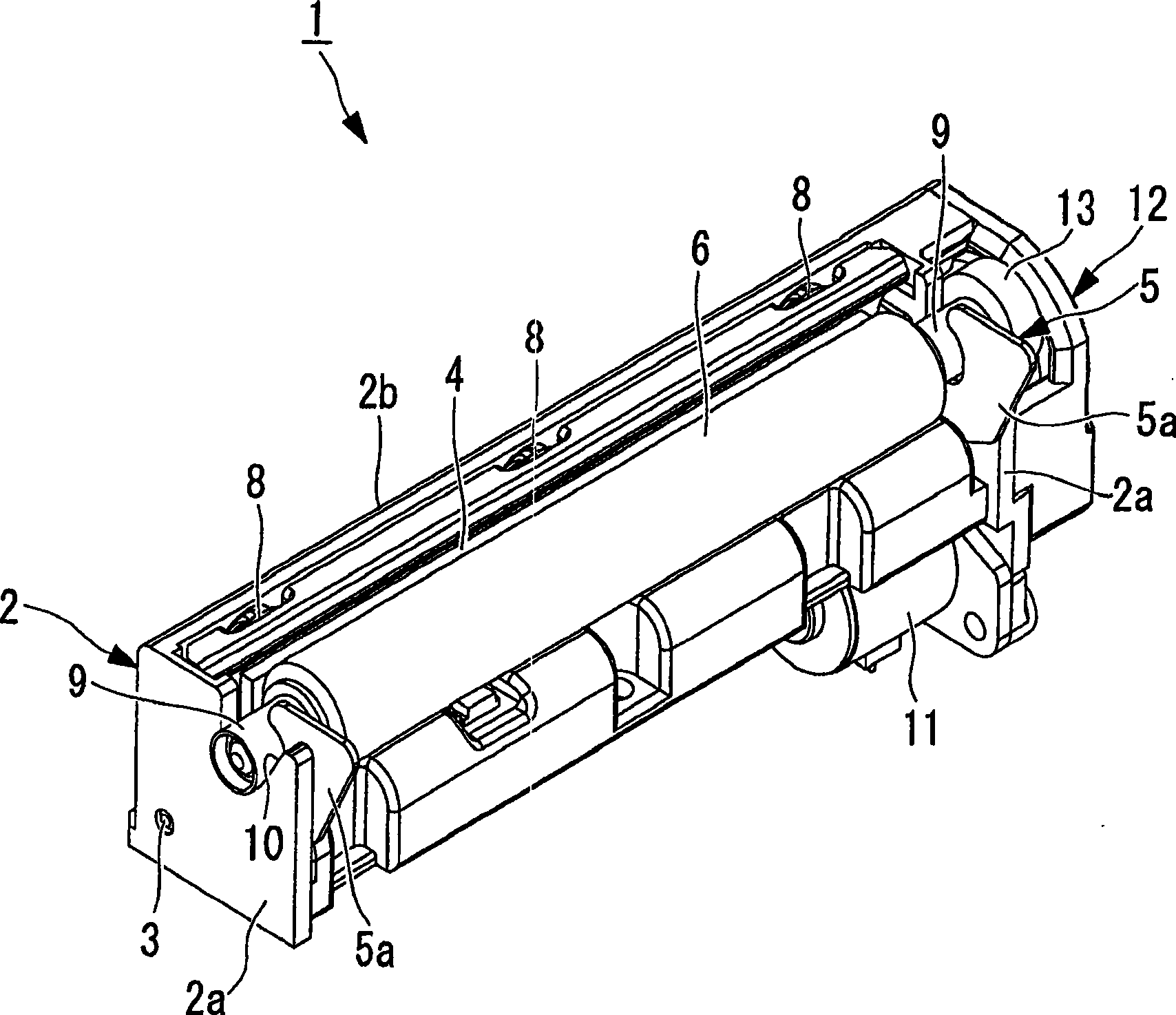
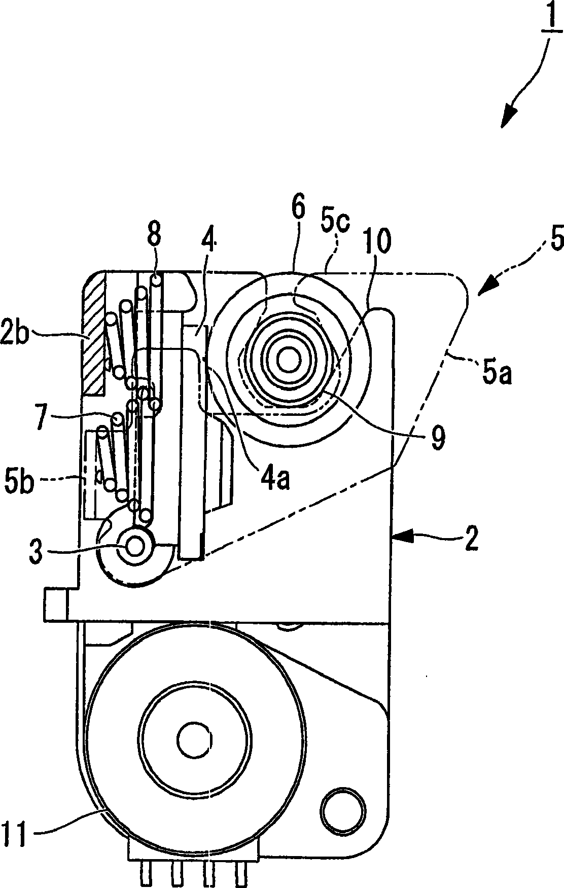
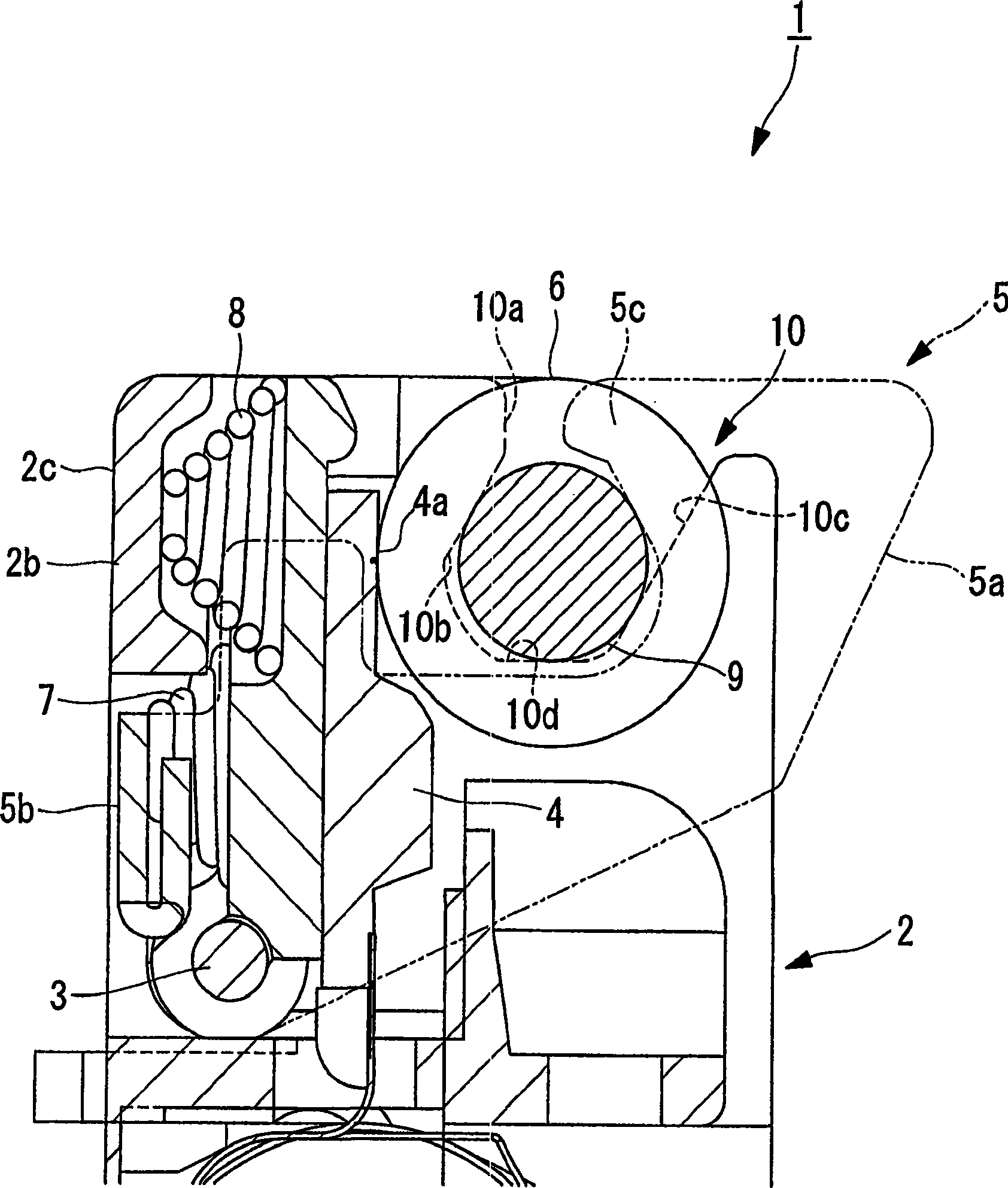
[0020] figure 1 is a perspective view showing the thermal printer according to this embodiment. figure 2 to show the installed figure 1 A longitudinal cross-sectional view of the state of the embossing roller of a medium thermal printing machine. image 3 for figure 2 A zoomed-in view of the main part of . 4A to 4B are views showing a state where the embossing roller and the bearing are moved to the side opposite to the shaft, wherein FIG. 4A is the same as image 3 Similar views, and Figure 4B is a further enlarged view of the main part in Figure 4A.
[0021] Such as figure 1 As shown, the thermal printer 1 of this embodiment comprises: a main body frame 2; a thermal head 4 and a locking arm 5 that is swingably installed on the concentric shaft (support shaft) 3 of the main body frame 2; supported by the locking arm 5 An embossing r...
PUM
Abstract
In order to prevent a platen roller and shaft bearings from accidentally coming off from notches to improve reliability of a thermal printer, Provided is a thermal printer, including: a main body frame (2); a thermal head swingably mounted to the main body frame (2); a platen roller (6) which is disposed so as to be opposed to a printing surface of the thermal head and sandwiches thermal paper with the thermal head to feed the thermal paper; and a lock arm (5) which is swingably mounted to a supporting shaft (3) mounted to the main body frame (2) and presses shaft bearings (9) rotatably supporting the platen roller (6) to a thermal head side to lock the platen roller (6) with notches (10) formed in the main body frame (2), in which the lock arm (5) is provided, on the tip end portion thereof, with a first inclined surface (5d) which, when the platen roller (6) and the shaft bearings (9) are moved toward openings of the notches (10), comes into contact with the outer peripheral surface of each of the shaft bearings (9) and generates a force in a direction of opening the lock arm (5).
Description
technical field [0001] The invention relates to a thermal printing machine. Background technique [0002] Generally, as a thermal printer, for example, a thermal printer disclosed in Patent Document 1 is known. In the thermal printing machine disclosed in Patent Document 1 (JP2000-318260A), the bearing for the bearing type backup platen roller is sandwiched between the notch formed on the side wall of the main body frame and the lock arm, thereby locking the The embossing roller is mounted on the main body frame. [0003] However, in the thermal printer described in Patent Document 1, a problem arises that when the thermal paper placed (set) between the thermal head and the platen roller is dragged by excessive force for cutting , the embossing roller and bearing thereby move to the side opposite to the support shaft, the embossing roller and bearing are turned (released) toward the direction of unlocking the locking arm and come off from the notch, thus making subsequent ...
Claims