Vehicle slide-door constraint structure

A technology of restraint structure and sliding door, which is applied in the direction of vehicle components, doors, transportation and packaging, etc., can solve the problems of increased number of components, increased cost, restraint structure can not be arranged in a limited space, etc., to achieve opening and closing operations The effect of smooth and reliable control

Inactive Publication Date: 2009-06-17
SUZUKI MOTOR CORP
View PDF1 Cites 13 Cited by
  • Summary
  • Abstract
  • Description
  • Claims
  • Application Information

AI Technical Summary

Problems solved by technology

Therefore, when a load is applied to the sliding door from the cabin side to the outside of the vehicle, for example, when equipment, passengers, cargo, etc. on the cabin side collide with the sliding door, a problem occurs that the movement of the sliding door cannot be effectively restricted.
Moreover, since a space for fixing the hook member must be secured, the restraint structure cannot be arranged in a limited space, so that there arises a problem that the application of the conventional restraint structure is limited to a specific vehicle type
Also, the hook member must be provided separately to restrict the movement of the sliding door, so the conventional restraint structure has a disadvantage of an increase in the number of parts, resulting in an increase in cost

Method used


Image

  • Vehicle slide-door constraint structure
  • Vehicle slide-door constraint structure
  • Vehicle slide-door constraint structure

Examples


Embodiment Construction

[0025] A restraint structure of a sliding door for a vehicle according to an embodiment of the present invention will be described in detail with reference to the accompanying drawings.

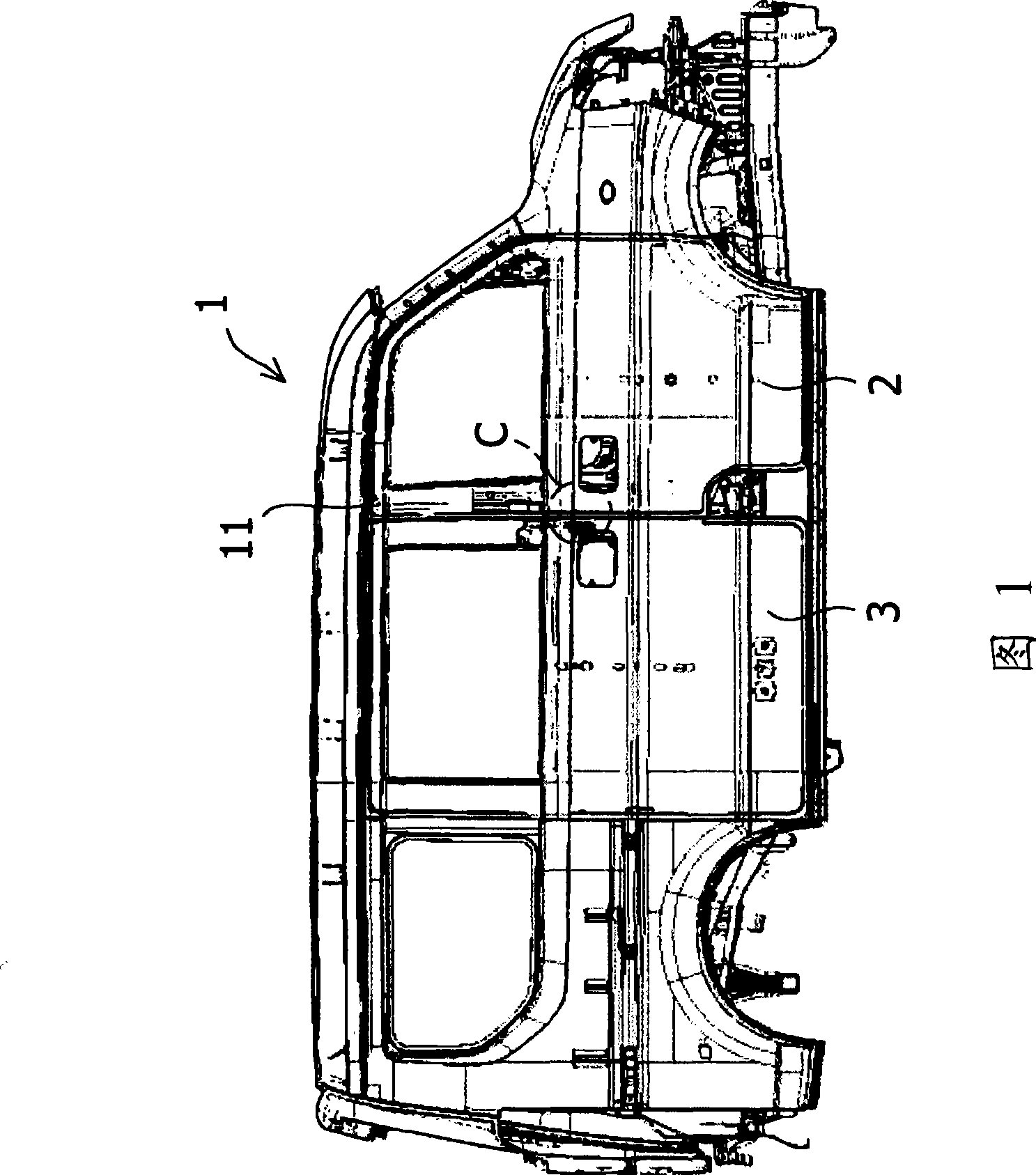
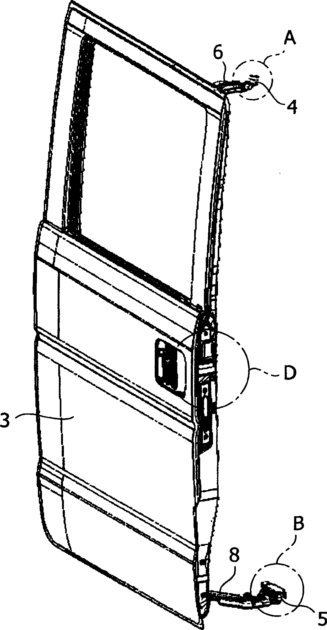
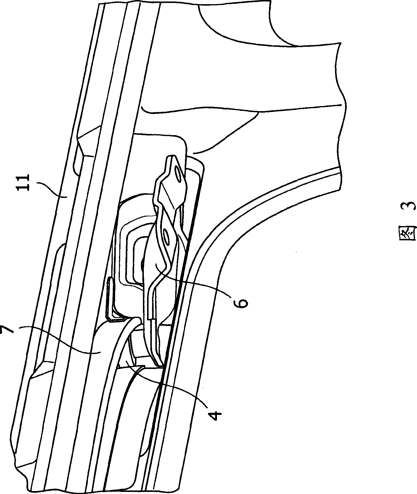
[0026] 1 is a side view of a motor vehicle to which a vehicle sliding door restraint structure according to an embodiment of the present invention is applied; figure 2 is a perspective view of the sliding door shown in Fig. 1 viewed obliquely from the exterior front side; Fig. 3 shows figure 2 An enlarged perspective view of the vicinity of part A in; Figure 4 is a diagram showing figure 2 Figure 5 is an enlarged perspective view of the vicinity of part B in Figure 1; Figure 5 is a perspective view of the car body side of part C in Figure 1 obliquely viewed from the exterior rear side; Figure 6 is shown obliquely seen from the external front side figure 2 The enlarged perspective view of the sliding door side of part D in Fig. 1 and part C in Fig. 1; Fig. 7 shows the Figure 6 The section...


PUM


Abstract

The invention provides a constrained structure of vehicle slide-door, capable of making the slide-door slide on the fore and aft direction of the vehicle to open and close the vehicle door opening at the side surface of the vehicle-body, wherein a latch lock is set on the vehicle-body side vertical wall surface facing the vehicle door opening and the latch lock is of U shape, observed from one side of the vehicle-body side surface; an insertion hole is set on the side vertical wall surface of the slide-door and the latch lock is inserted into the insertion hole when the slide door is closed; and a pair of notch parts capable of being jogged with the latch lock at a cabinet side of the insertion hole, when the load is applied on the slide-door from the cabinet side towards the outside of the cabinet, the latch lock is partly jogged with the notch parts by the insertion hole. Thus, even though it is difficult to ensure the space, when the load is applied on the slide-door towards the outside of the cabinet, the slide-door is constrained to effectively constrain the movement of the slide-door without prejudice to normal opening and closing operation of the slide-door.

Description

technical field [0001] The present invention relates to a restraint structure of a sliding door of a vehicle, which improves the holding strength of the sliding door against a load applied from a cabin side. Background technique [0002] Generally, a sliding door is provided at the side of the vehicle body to open and close the door opening at the side of the vehicle body by sliding in the front-rear direction of the vehicle. This sliding door is disclosed in JP 2006-35881 A, for example. [0003] With the above-mentioned sliding door, a latch protruding toward the door opening side is provided in the vertical direction on the vertical surface of the opening end edge of the door opening; and corresponding to the latch, a latch is provided on the door end surface facing the vertical surface. A hook member bent toward the cabin side and equipped with engaging claws. When the vehicle door is closed, the engaging pawl of the hook member faces the latch from the outside of the ...

Claims


Application Information

Patent Timeline
Patent Type & Authority Applications(China)
IPC IPC(8): B60J5/06
Inventor 铃木仁志芳贺高宏武田浩典
Owner SUZUKI MOTOR CORP
Why Eureka
Try Eureka