
Interlock mechanism

A locking mechanism and keyhole technology, which is applied in building locks, connecting components, mechanical equipment, etc., can solve the problem of being unable to simultaneously lock the body of a portable electronic device and the expansion device, and achieve the effect of preventing people from stealing

Inactive Publication Date: 2009-06-24
程艳丽
View PDF1 Cites 4 Cited by
  • Summary
  • Abstract
  • Description
  • Claims
  • Application Information

AI Technical Summary

Problems solved by technology

[0009] In view of the above problems, the present invention provides a locking mechanism, which can only prevent the portable electronic device body or a single device of the expansion device from being stolen, but cannot lock the portable electronic device at the same time. The defects of the device body and the expansion device have been improved

Method used


Image

  • Interlock mechanism
  • Interlock mechanism
  • Interlock mechanism

Examples


Embodiment Construction

[0033] The locking mechanism disclosed in the present invention is disposed in an electronic device, and the electronic device includes but is not limited to a desktop computer, a notebook computer, a server, etc., which can be externally connected to at least one mobile device. In the following detailed description of the present invention, a notebook computer will be taken as the preferred embodiment of the present invention. However, the accompanying drawings are provided for reference and illustration only, and are not intended to limit the present invention.

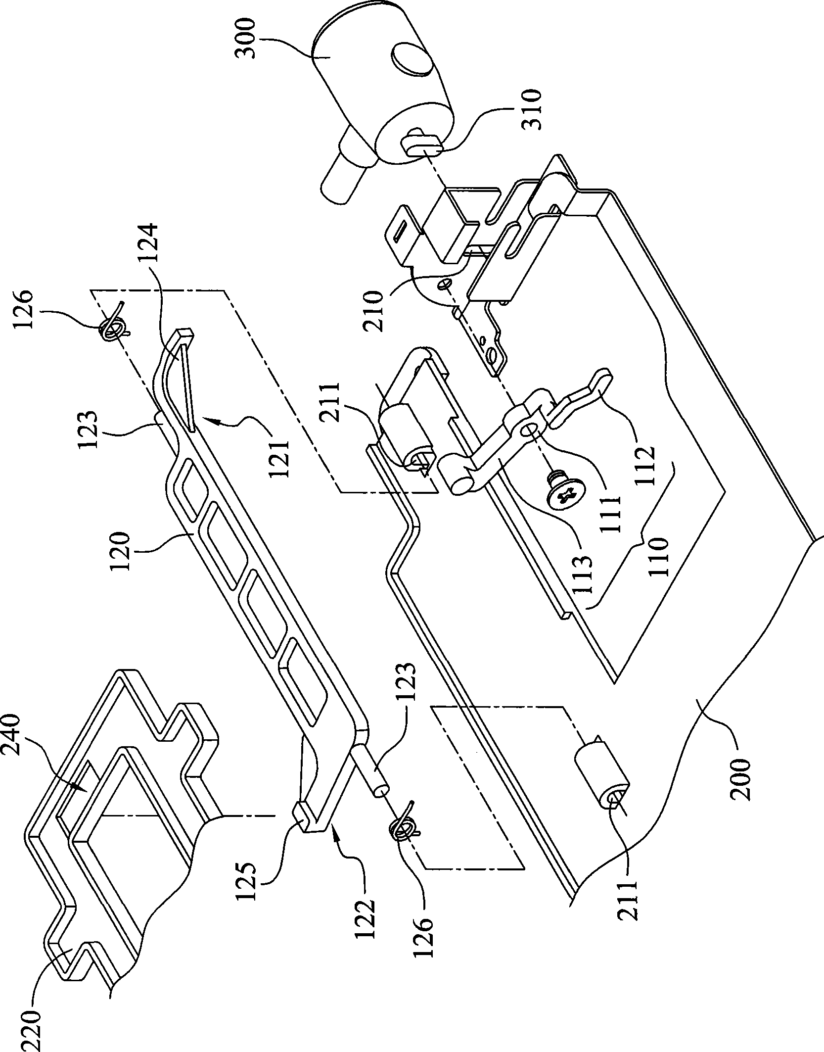
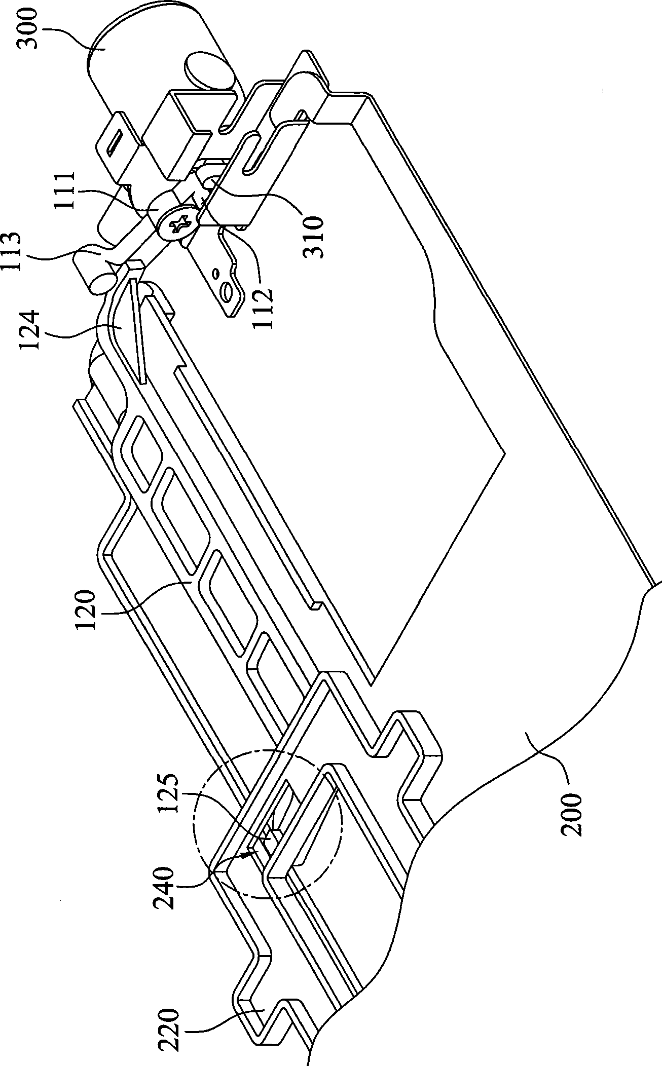
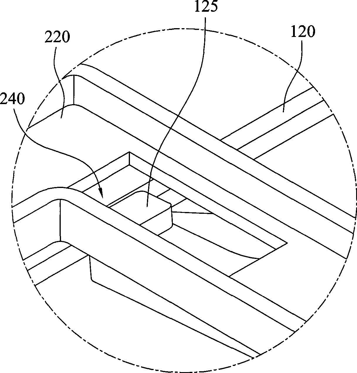
[0034] Figure 1 to Figure 3 It is a three-dimensional schematic diagram of the first embodiment of the present invention. As shown in the figure, the locking mechanism disclosed in the present invention is set in an electronic device, a lock hole 210 is provided on the housing 200 of the electronic device, and a lock 300 is installed at the position of the lock hole 210, and the lock 300 has a locking tongue 310 ...


PUM


Abstract

The invention relates to a lock catch mechanism. The mechanism is arranged in an electronic device and enables a movable device to be fixed in the electronic device through a lock tongue of a lock set. The mechanism comprises a linkage rod and a buckle piece and is pivoted in a casing of the electronic device; a first end of the linkage rod is in contact with the lock tongue; a second end of the linkage rod corresponds with a third end of the buckle piece; a fourth end of the buckle piece; a stopping part is arranged at a forth end of the buckle piece; the linkage rod pushes the buckle piece through the rotation of the lock tongue, so as to drive the stopping block of the buckle piece to extend into a limiting hole of a movable device, so that the movable device can not withdraw from the electronic device.

Description

technical field [0001] The invention relates to a locking mechanism, in particular to a locking mechanism for locking a movable device in an electronic device. Background technique [0002] Most of the currently seen computers are equipped with at least a part of the data reading device, such as a floppy disk drive, an optical disk drive (ODD) or a recorder, so as to play multimedia video files or read and write a large number of data files. [0003] Taking a notebook computer as an example, in order to maintain the advantages of light weight and easy portability of the notebook computer, the optical drive originally built in the computer device is installed in the multi-function expansion slot (MultiBay) of the notebook computer in an external connection mode, and the optical drive can be Hot-swappable directly from the notebook computer, which is convenient for users to quickly replace different external reading devices. [0004] In addition, in order to enhance consumers...

Claims


Application Information

Patent Timeline
IPC IPC(8): G06F1/18H05K7/00F16B21/02E05B73/00
Inventor 卓钰祺
Owner 程艳丽
Learn More