Method and device for self-help drawing money

A self-service withdrawal and automatic withdrawal technology, which is applied in the direction of complete banking system, complete banking system, coinless or similar appliances, etc., can solve the problems of wasting time, inconvenient operation, etc., achieve convenient renewal and improve efficiency Effect

Active Publication Date: 2009-06-24
BEIJING RINRONG TECH
View PDF0 Cites 0 Cited by
  • Summary
  • Abstract
  • Description
  • Claims
  • Application Information

AI Technical Summary

Problems solved by technology

[0002] The current method of batch ATMs is to bundle them up and put them into the storage unit manually, which makes the operation very inconvenient and wastes time.

Method used


Image

  • Method and device for self-help drawing money
  • Method and device for self-help drawing money
  • Method and device for self-help drawing money

Examples


example 1

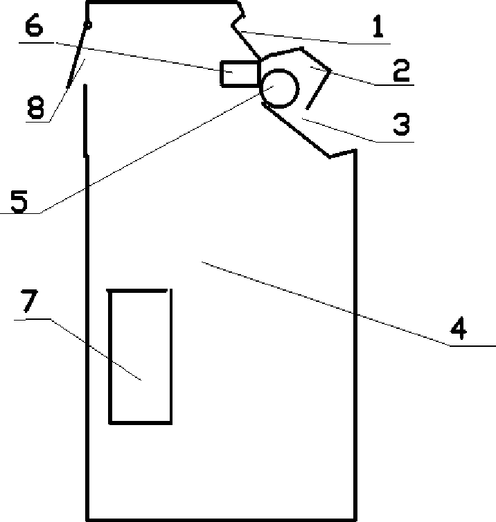
[0060] see figure 1 It consists of 5 storage units, the specific structure of which can be seen in the method and device of an intelligent storage unit applied for on December 12 this month. It is located at the exit of the box and is used to authorize the main control machine to control depositing cash bundles and paying cash bundles. , the renewal device 6 is connected with the entrance of the storage unit set, and is used to grant the control of the main control machine, and is responsible for adding the money to the storage unit of the storage unit set. The main control machine 7 is connected to the front-end server of the bank through a dedicated network It is connected to and controls the payment terminal, which is used to obtain the card information through the card reader and report it to the bank, accept the customer's instruction through the keyboard, deduct the money from the customer's account at the bank, and instruct the storage unit Payment; display 1, installed...

example 2

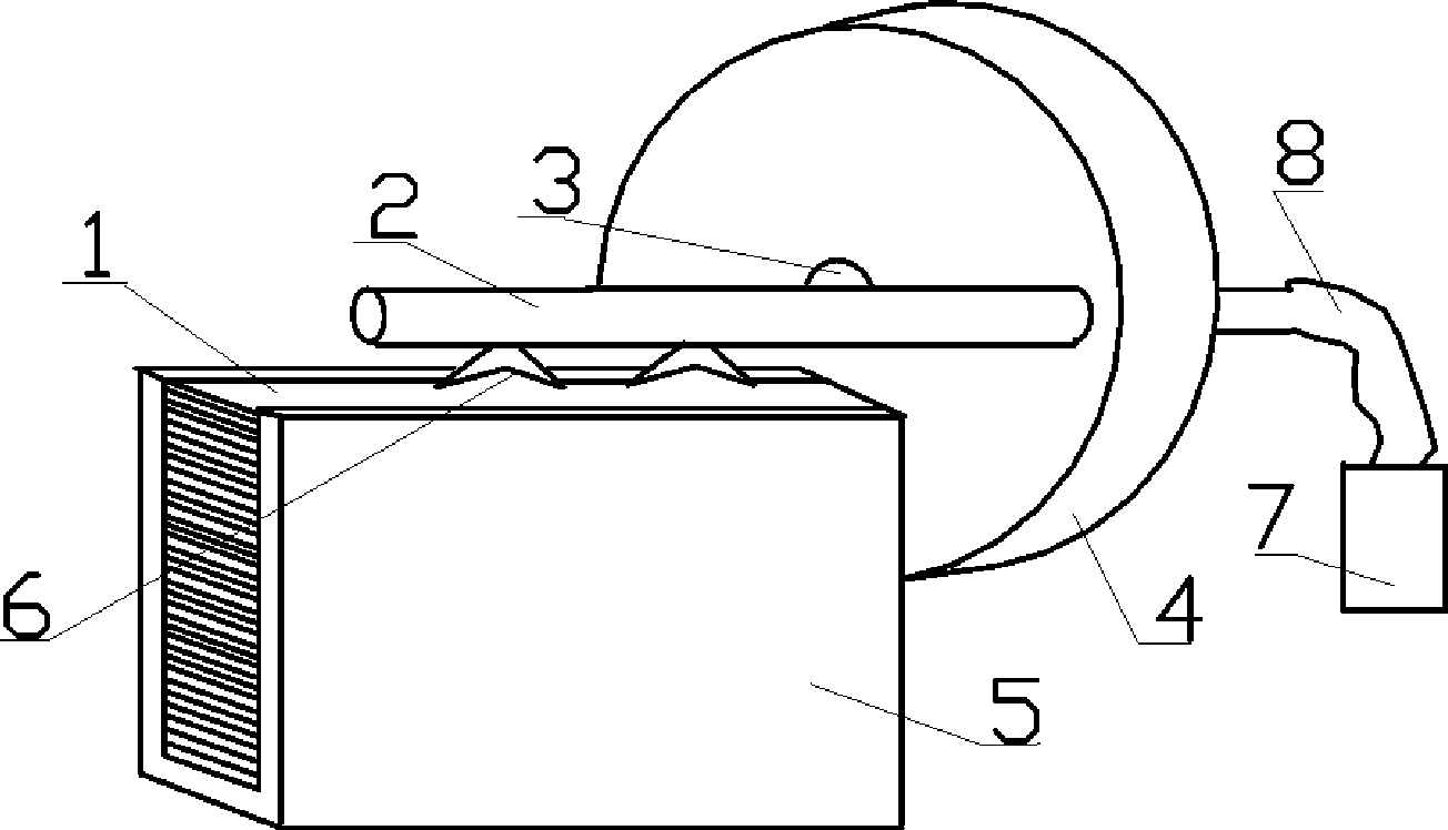
[0066] Figure 6 As shown, 1 is a bundle of banknotes, 2 is an air suction pipe with an air suction nozzle, 6 is an elastic air suction nozzle, 13 is a storage unit, 12 is a connection between a cam and a drive motor, and 12 can also be an electromagnet for The movable rod 11 of driving clamp, 11 is the movable rod of clamp, is fixed on the shaft 14, is used for rotating around this shaft, can make clamp open mouth and close mouth, and 15 is the other foot of clamp, is fixed on the rotating shaft 14 is fixedly connected with the rotating shaft, and is used for swinging with the rotating shaft. When the adsorption rod is sucked into the cash bundle, it swings clockwise to the vicinity of the clamp, and the clamp receives the cash bundle, and the clamp swings clockwise, as Figure 7 Feed bundles of cash into the storage unit.

[0067] Figure 7 Among them, 28 is the bundle of banknotes, 21 is the entrance of the storage unit, the cam mechanism turns to the upper end around the...

example 3

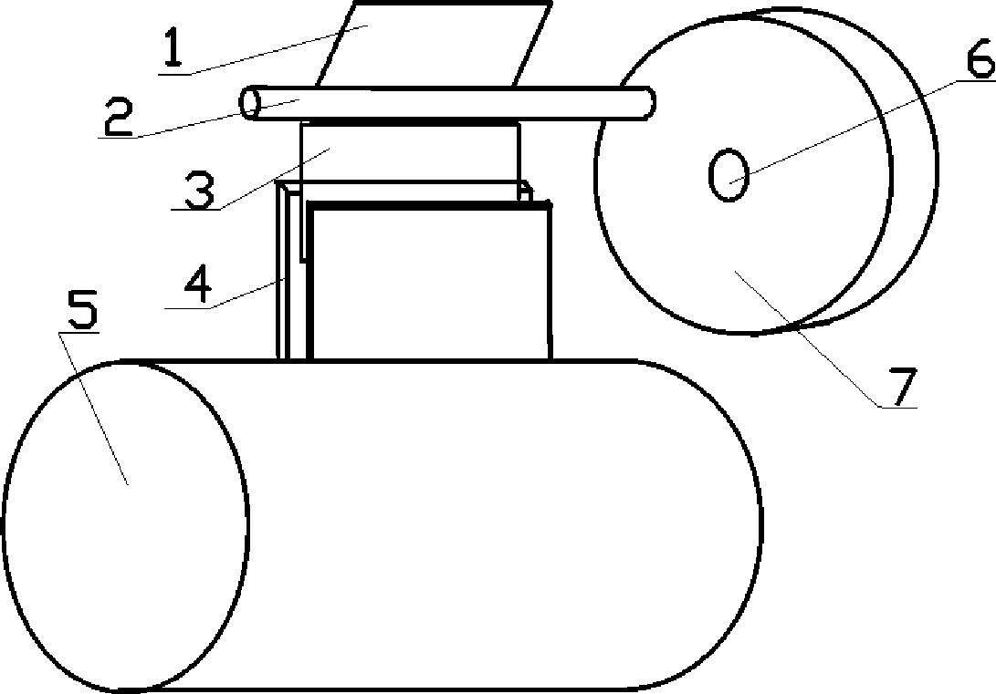
[0071] Figure 10 As shown, 2 is the cash bundle, 1 is the binding belt; the manipulator is a thin insert, 3 is the tip of the insert, 4 is the insert, and 5 is the driving rod. Use a driving mechanism to let it press the cash bundle first. Then insert it into the binding strap of the cash bundle, pick up a bundle, and then put it into the storage unit, and the others are the same as the above examples.

[0072] Such as Figure 11 Among them, 1 is the replacement cash box, and the front end of the bottom is provided with a groove, which is used for pushing out the bundle of banknotes by the push-out mechanism. At the bottom, 8 is a side plate, and 10 is a push-out part, which is connected with the push-out mechanism and is used to jack up a bundle of cash. The thickness of the bundle of cash in the box of each bundle of cash is fixed, so the provided slot , should be just in the middle of the banknotes placed at the head, 11 is the cash bundle driving mechanism, 31 is the ej...


PUM


Abstract

The invention provides a self-service withdrawal method and the device thereof; the device comprises a withdrawal terminal and a terminal main control computer; wherein, the main control computer is connected with front-end computers of a bank special network; and the withdrawal terminal performs the function according to the following steps: different denominational cash is bundled or packaged according to certain amount; the cash is put to the withdrawal device; the withdrawal device put the bundled cash to a storage unit; each storage unit is put into a bundle; the main control computer records deposits and corresponding storage unit address; each storage unit is provided with a corresponding address coding or a corresponding coordinate coding; in withdrawing, the withdrawal device reads the information of a client and reports the information to a bank terminal server for verifying the identity; the client keys the cash denomination and amount which are planned to take out to the withdrawal terminal; the main control computer reports the denomination and amount to the bank terminal server and calculates the address or the coordinate coding (such as if withdrawing 10,500 Yuan, abundle of 10,000 Yuan and a bundle of 500 Yuan can be withdrawn) of the corresponding denomination and amount in a withdrawal device after authorizing, and the main control computer instructs the withdrawal device to pay.

Description

technical field [0001] The invention belongs to the field of automatic withdrawal, in particular to a method and device for self-service withdrawal. Background technique: [0002] The method of present batch automatic teller machine is to adopt to tie up, and has artificially to put into storage unit, puts time like this, and operation is very inconvenient, wasted time. Invention content: [0003] The object of the present invention is to solve the above-mentioned problems. The scheme that the present invention solves its technical problem adopts is: establish withdrawing terminal and terminal main control machine, this main control machine is connected by the front-end machine with bank special network, and withdrawing terminal carries out according to the following steps: [0004] 1. Bundle or package cash of various denominations according to a certain amount; for example, 10 yuan / bundle of 1-yuan denomination of coins; 5 yuan / bundle of 5-cent denomination; 500 yuan / bu...

Claims


Application Information

Patent Timeline
Patent Type & Authority Applications(China)
IPC IPC(8): G07F19/00
Inventor 陆洪瑞
Owner BEIJING RINRONG TECH
Why Eureka
Try Eureka