Method of manufacturing disposable wearing article

A manufacturing method and article technology, which is applied in the field of disposable wearable article manufacturing, can solve problems such as not being disclosed, and achieve the effect of reducing cutting

Active Publication Date: 2009-06-24
ZUIKO CORP
View PDF4 Cites 6 Cited by
  • Summary
  • Abstract
  • Description
  • Claims
  • Application Information

AI Technical Summary

Problems solved by technology

[0009] However, in Patent Document 2, it is not disclosed that when the complex is cut into individual products, it can be cut into T-shaped diapers.

Method used


Image

  • Method of manufacturing disposable wearing article
  • Method of manufacturing disposable wearing article
  • Method of manufacturing disposable wearing article

Examples


Embodiment 1

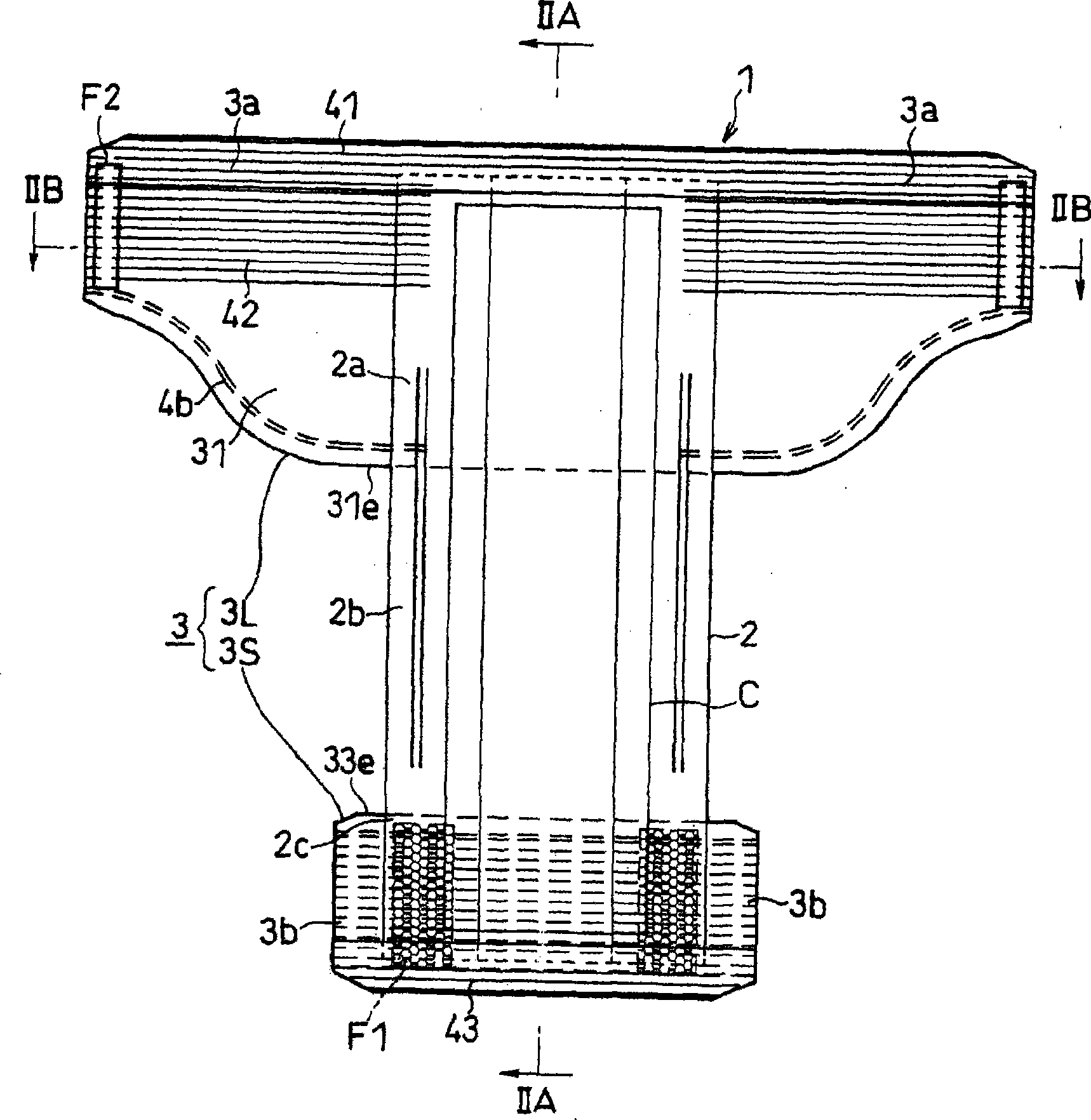
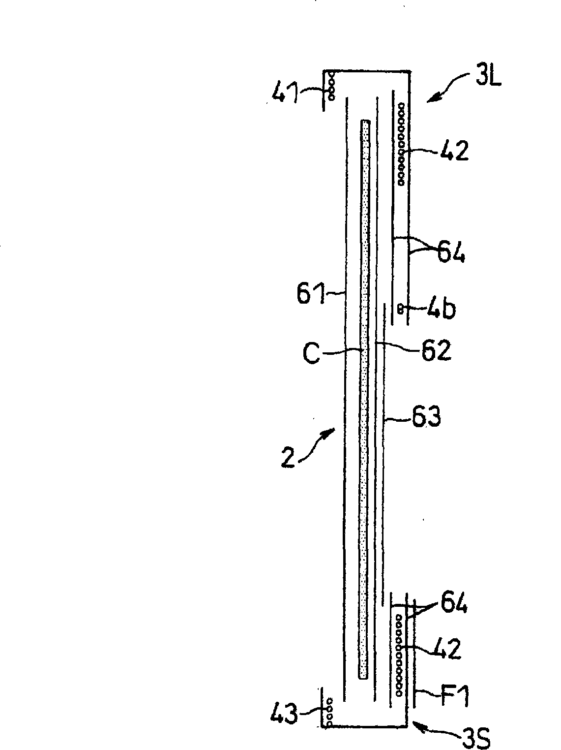
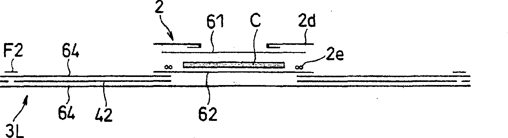
[0041] exist figure 1 Among them, the diaper 1 is integrally formed of a central part 2 and a body part 3 having a length greater than the width of the central part 2 .

[0042] The trunk portion 3 is composed of a back portion 3L that is longer in the direction around the trunk, and a front portion 3S that is shorter than the back portion 3L in the direction around the trunk.

[0043] The above-mentioned central part 2 is arranged so as to straddle between the back part 3L and the front part 3S. The shape of the lower end 31e of the buttocks (hip (hip)) 31 of the back 3L is substantially the same as the shape of the lower end 33e of the front part 3S.

[0044]In this diaper 1, the central part 2 is integrally formed of a root part 2a which overlaps and joins with the back part 3L, a crotch part 2b which closely fits between the wearer's crotches, and a front end part 2c which overlaps and joins with the front part 3S. form.

[0045] That is, in the above-mentioned central ...

Embodiment 2

[0108] Figure 6 Shown is Example 2.

[0109] In this embodiment, in addition to the steps in the method of the first embodiment, a cutting step of cutting a part T1 of the sheet material to reduce the area covering the wearer's buttocks is further included.

[0110] The first cutout portion T1 is formed by cutting and removing a portion between the first cutting line CL of the first split piece W1 and the first cutting line CL of the second split piece W2 facing each other.

[0111] The cutting process of cutting out the said 1st cutting part T1 can be performed at arbitrary timing.

[0112] However, it is preferable that the cutting step and the step of dividing the sheet W are performed simultaneously. This is due to the ability to use only one cutting drum for severing.

[0113] In addition, in this manufacturing method, you may cut out the 2nd cutout part T2.

[0114] The said 2nd trimming part T2 is formed by cutting and removing between the front part 3S and back pa...

Embodiment 3

[0117] Figure 7 ~ Figure 9 Shown is Example 3. The structure of the diaper of Example 3 is demonstrated.

[0118] In the present embodiment, flap pieces 37 are respectively joined to both end portions of the wing portions 3a, 3a in the direction surrounding the trunk.

[0119] The length of the flap piece 37 is the actual length of the back 3L in the direction around the trunk.

[0120] Such as Figure 8B As shown, the flap piece 37 is joined to the wing portion 3 a at a joining line 37 a at the proximal end of the wing portion 3 a in the direction around the trunk.

[0121] The flap piece 37 extends from the joining line 37a toward the center portion 2 in a direction surrounding the trunk.

[0122] A second hook-and-loop fastener F2 is attached to the end of the flap piece 37 opposite to the joining line 37a.

[0123] The second hook-and-loop fastener F2 is engaged with the inner surface of the back portion 3L to falsely join the wing portion 3 a and the flap piece 37 ....


PUM


Abstract

To provide a method of manufacturing a T-shaped wearing article less like to leave waste material. [MEANS FOR SOLVING THE PROBLEMS] A web (W) is divided into a first divided sheet (W1) and a second divided sheet (W2) by slitting the web along a predetermined first cutting line (CL). The first divided sheet (W1) and the second divided sheet (W2) are separated from each other. A core part (2) is disposed between the first divided sheet (W1) and the second divided sheet (W2) to form a composite body (10). Respective divided sheets (W1, W2) are so cut along a transverse second cutting line (Ch) that the portions of the sheets forming back parts (3L) are longer than the portions forming front parts (3S) in the conveying direction (X) of the divided sheets (W1, W2).

Description

technical field [0001] The present invention relates to a method for manufacturing disposable wearing articles such as so-called T-shaped (belt type) diapers. Background technique [0002] In the following patent document 1, the method of manufacturing the said T-shaped diaper using so-called cross flow is disclosed. [0003] On the other hand, Patent Document 2 below discloses a method of producing H-shaped diapers and underpants using cross flow. [0004] Patent Document 1: Japanese Special Examination No. 2005-519675 (Abstract of Specification) [0005] Patent Document 2: WO 2005 / 004776A1 (FIG5) [0006] In the invention of the above-mentioned Patent Document 1, when the complex is cut into wearing articles, the back part is longer than the front part by cutting the composite body into a belt-shaped wearing article. [0007] However, in the aforementioned Patent Document 1, since the leg holes are formed by diecutting the wearing article, material waste occurs. [000...

Claims


Application Information

Patent Timeline
Patent Type & Authority Applications(China)
IPC IPC(8): A61F13/15A61F13/49A61F5/44
CPCA61F13/15804A61F13/15723A61F13/49A61F13/496A61F2013/49063A61F13/15756Y10T156/1067
Inventor 和田隆男
Owner ZUIKO CORP
Why Eureka
Try Eureka