Illuminating apparatus of motorcycle

A lighting device, motorcycle technology, applied in bicycle accessories, transportation and packaging, optical signals, etc., can solve the problems of insufficient light, danger, poor recognition effect, etc., and achieve the effect of improving safety and improving the recognition rate

Inactive Publication Date: 2009-07-01
KYMCO
View PDF1 Cites 8 Cited by
  • Summary
  • Abstract
  • Description
  • Claims
  • Application Information

AI Technical Summary

Problems solved by technology

[0006] Since the headlight 141 and the fog lamp 15 of the illuminating device 14 are located on the same straight line 10 at the same time, the light projected by the headlight 141 and the fog lamp 15 produces cross interference so that the fog lamp 15 and the headlight 141 The lighting effect is greatly reduced
[0007] 2. Poor identification effect:
Thus, the light rays of the two direction lights 142 are often shaded by the brightness of the headlight 14, and the light rays projected by the headlight 141 and the fog lamp 15 intersect and cannot be concentrated on the same point, resulting in Disadvantages of greatly reduced lighting effects
[0010] But, this headlight 141, these direction lights 142, and described fog lamp 15 are arranged on this vehicle body 11 simultaneously, when turning, this headlight 141, described direction lamp 142, and described fog lamp 15 place The projected light source cannot turn in time with the direction of the front of the vehicle 12, resulting in insufficient light when turning, and it is difficult to identify the danger of road conditions in time, and each direction light 142 and the corresponding fog light 15 are integrated into a module, causing each direction. The light 142 is within the light irradiation range of the corresponding fog lamp 15, but the light of the two direction lights 142 is often covered by the brightness of the corresponding fog lamp 15, making it difficult for the driver to recognize the direction of turning. On the contrary, it poses a danger on the road
Therefore, this improvement is not a good strategy

Method used


Image

  • Illuminating apparatus of motorcycle
  • Illuminating apparatus of motorcycle
  • Illuminating apparatus of motorcycle

Examples


Embodiment Construction

[0021] The aforementioned and other technical contents, features and effects of the present invention will be clearly presented in the following detailed description of a preferred embodiment with accompanying drawings.

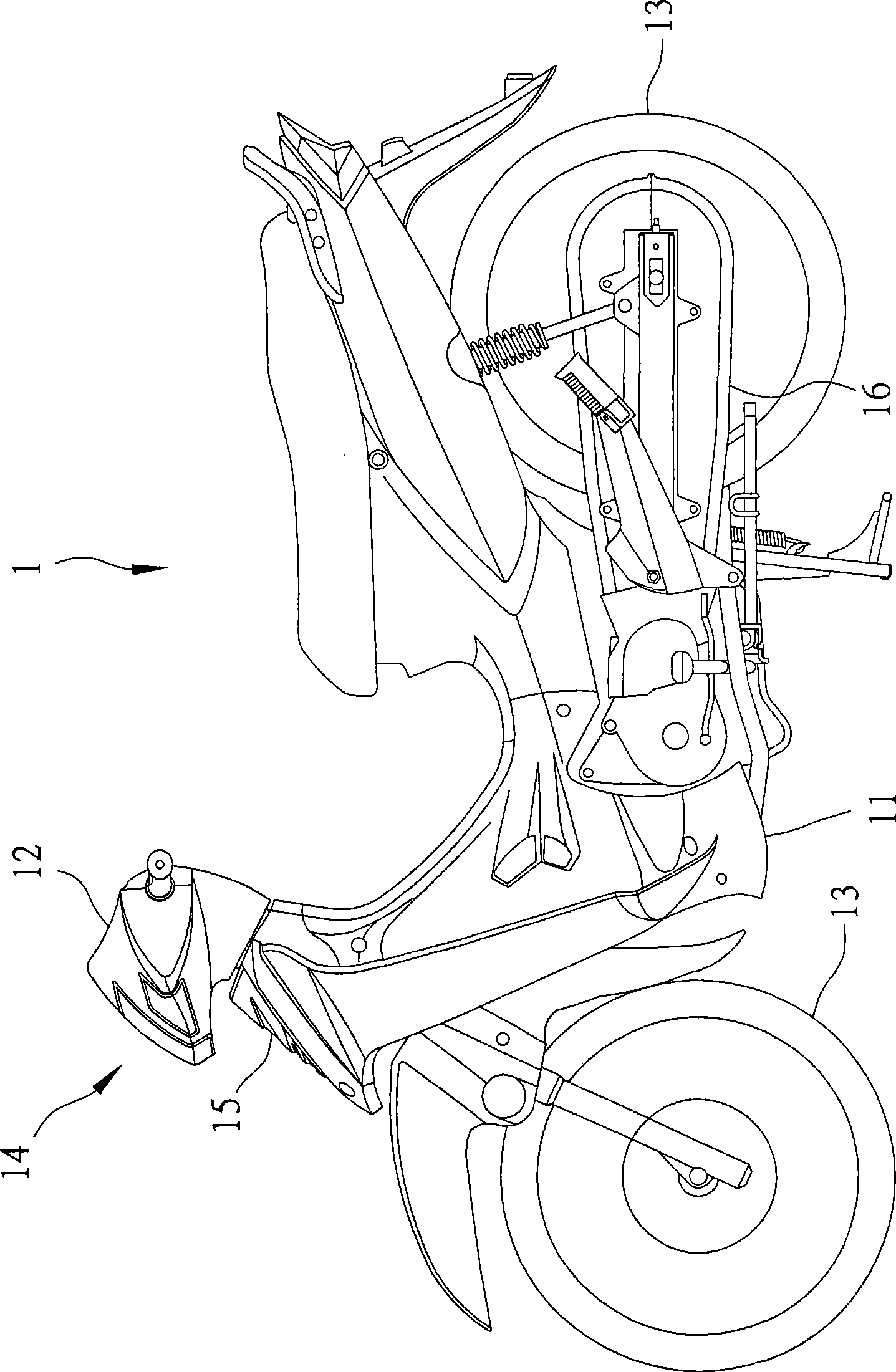
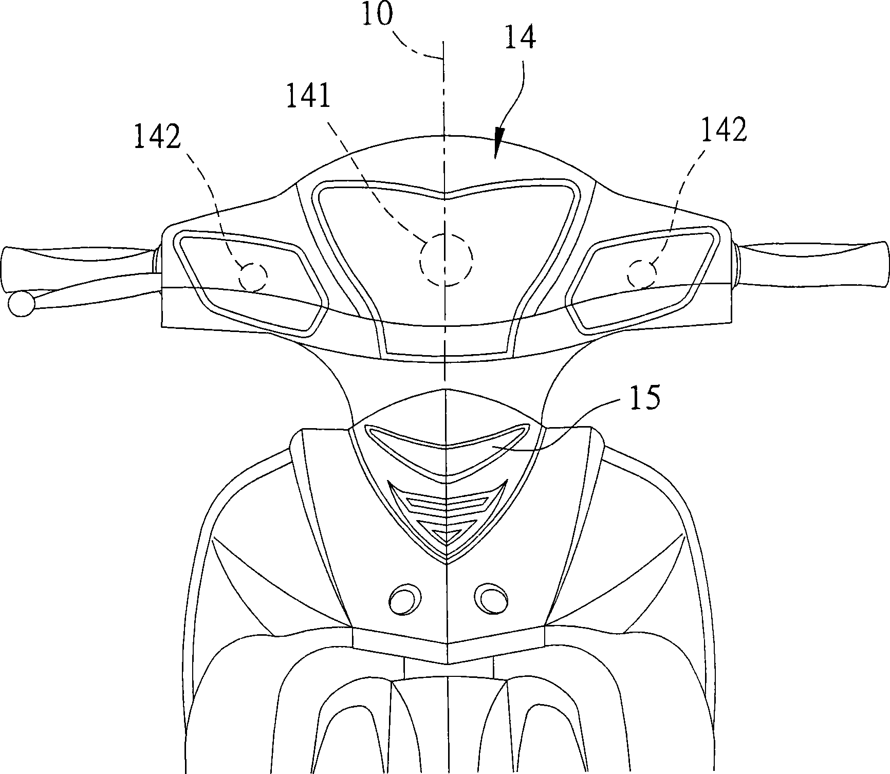
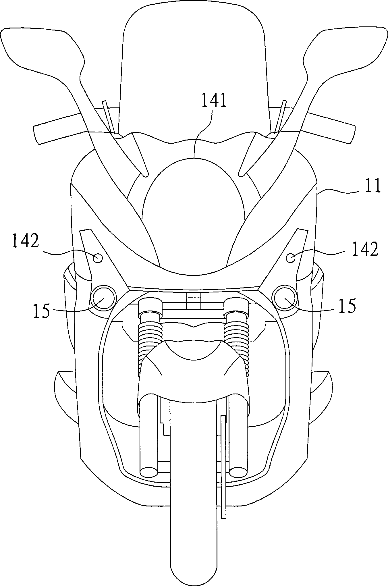
[0022] refer to Figure 4 and Figure 5 , the preferred embodiment of the lighting device 3 of the present invention is installed on a motorcycle 2, and the motorcycle 2 includes a car body 21, a headstock 22 pivotally arranged on the car body 21, a car body 21 Front wheel 23 at the front end, a rear wheel 24 that is arranged at the rear end of the vehicle body 21 opposite to the front wheel 23, and a power group 25 for driving the front wheel 23 and the rear wheel 24, wherein the vehicle The body 21 has a front cover 211 , and the front 22 has a front cover 221 .

[0023] The lighting device 3 includes a headlight group 31 arranged on the front cover 221, two position lamp groups 32 arranged at intervals on the front cover 211 of the vehicle body, and two ...


PUM


Abstract

The invention discloses a lighting device for a motorcycle. The motorcycle comprises a vehicle body, a vehicle head pivoted on the vehicle head, a front wheel arranged at the front end of the vehicle body, a rear wheel arranged at the rear end of the vehicle body opposite to the front wheel and power unit driving the front wheel and a rear wheel. The vehicle body is provided with a vehicle body front cover, and the vehicle head is provided with a vehicle head front cover. The lighting device comprises a headlight set, as least one position light set and two directional light sets. The headlight set is arranged on the vehicle head front cover, and the position light set and the directional light sets are arranged on the vehicle front cover. The light beams projected from the large light set, the position light set and the directional light sets do not interfere one another. Thus, the identification rate of the motorcycle is improved and the riding safety of the motorcycle is improved effectively.

Description

technical field [0001] The invention relates to an illuminating device, in particular to an illuminating device for a motorcycle. Background technique [0002] Such as figure 1 , 2 As shown, the motorcycle 1 of the prior art includes a car body 11, a headstock 12 pivotally arranged on the car body 11, two wheels 13 pivotally arranged on the car body 11 at intervals, and a wheel 13 arranged on the car body 12 at intervals. A lighting device 14, a fog lamp 15 arranged on the vehicle body 11, and an engine 16 arranged on the vehicle body 11 to drive the two wheels 13 to rotate. [0003] The illuminating device 14 has a headlight 141 arranged on the headlight 12, and two direction lights 142 which are arranged on the headlight 12 at intervals and are located on two opposite sides of the headlight 141, wherein the headlight 141 and the headlight 141 The fog lamps 15 are located on the same straight line 10 . [0004] Wherein, although the lighting device 14 can achieve the ba...

Claims


Application Information

Patent Timeline
Patent Type & Authority Applications(China)
IPC IPC(8): B62J6/02
Inventor 吴文湧颜荣良
Owner KYMCO
Why Eureka
Try Eureka