A system and method for judging the location of the locomotive in the train

A technology for locomotives and trains, which is applied in the fields of railway car body parts, vehicle route interaction equipment, railway signals and safety, etc. Improved performance and timeliness, not easy to interfere with each other, and not easy to interfere with vehicles

Active Publication Date: 2022-01-21
ZHUZHOU CSR TIMES ELECTRIC CO LTD
View PDF22 Cites 0 Cited by
  • Summary
  • Abstract
  • Description
  • Claims
  • Application Information

AI Technical Summary

Problems solved by technology

Among them, the axle counting detection method is the most widely used and the most mature, but this method cannot distinguish whether each car in the train is a locomotive or a freight car
Since the ground automatic over-phase separation device needs to consider various train marshalling methods, in the end, the length of the neutral zone becomes longer, sometimes exceeding 1000m, which is not conducive to the troubleshooting and maintenance of the over-phase separation device
In addition, the infrared beam and catenary detection methods can theoretically directly detect the position of the locomotive (that is, the position of the pantograph), but due to the constraints of the weather environment, driver operation, and line operation conditions, engineering cannot meet the reliability requirements. No use report yet
[0005] In addition, there are other ways to detect the position of the train locomotive in the existing ground automatic phase separation device as follows: First, using the axle counting sensor to realize the train position identification, it is difficult to distinguish the locomotive from the trailer, and it is easy to cause the axle counting sensor to have wrong codes. The ground automatic phase separation device cannot accurately identify the position of the train and other issues; secondly, the reader is installed on the electric locomotive, and the reader is connected to the on-board phase separation equipment. When the electric locomotive passes through the commutation point, the reader is connected to the electronic tag wirelessly Communication, to know the position of the train locomotive, but due to the specific position settings of the reader and the electronic tag, the vehicle-mounted over-phase equipment is only applicable to the vehicle scene, and cannot be applied to the ground automatic over-phase system set in the neutral zone; third, use The open-hole sensor used to detect the catenary current is installed on the catenary at the monitoring point, that is, the catenary passes through the sensor, and when the train passes by, the secondary side of the sensor induces a current, thereby Drive the optical fiber launch head to output the train position information, but this method has no mature detection equipment, which is easily interfered by the meeting of the upper and lower trains, so that the train position cannot be accurately identified; Set up three anchor section joints, detect whether the locomotive current is present or not through the current transformers installed on the two neutral sections, and judge the actual position of the neutral section where the locomotive is located, as the basis for the automatic over-phase circuit breaker opening and closing operation, but this In this way, before the commutation operation control switch is closed, the position of the locomotive cannot be detected through this scheme, so it needs to cooperate with other detections, and this scheme needs to transform the existing catenary into three anchor joints, which requires a large amount of engineering

Method used


Image

  • A system and method for judging the location of the locomotive in the train
  • A system and method for judging the location of the locomotive in the train
  • A system and method for judging the location of the locomotive in the train

Examples


Embodiment 1

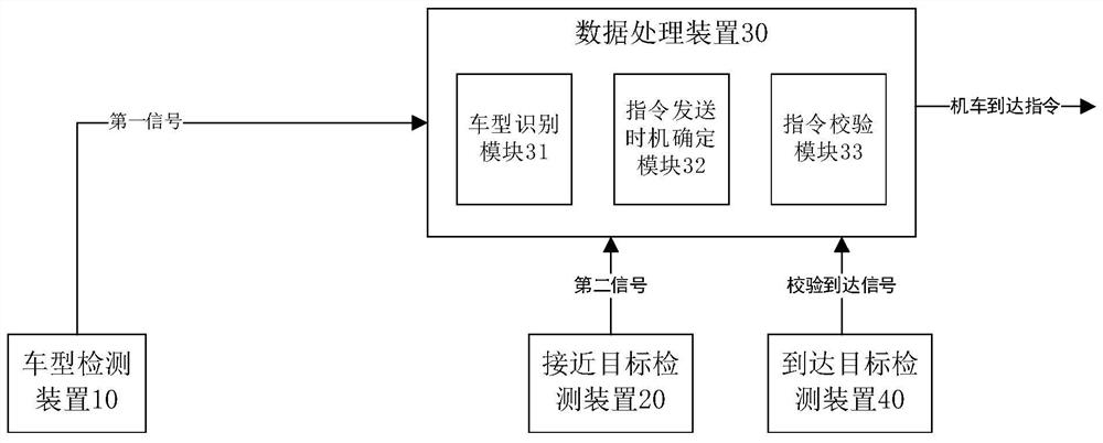
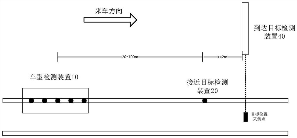
[0036] figure 1 It is a structural block diagram of a system for judging locomotive positions in a train according to an embodiment of the present application. Such as figure 1 As shown, the locomotive position determination system of the present invention at least includes: a vehicle type detection device 10 , an approaching target detection device 20 and a data processing device 30 . Specifically, the vehicle type detection device 10 is installed on the track at the first position, and is used for collecting a first signal containing wheelbase information between front and rear wheels of the train when the train arrives at the first position. Wherein, the target position (collection point) is the final position collection point of whether the locomotive to be identified in the train arrives, the first position is located on the entry side of the train compared to the target position, and the distance between the first position and the target position is preset. the first d...

Embodiment 2

[0056] On the basis of the above-mentioned embodiment one, refer to figure 1 , in the embodiment of the present invention, the locomotive position judging system further includes: an arrival target detection device 40 . Arrival target detection device 40 is set at the target position, and is used to detect in real time whether the locomotive to be identified has arrived at the target position, so as to verify the locomotive arrival instruction generated by vehicle type detection device 10 and approaching target detection device 20 . The present invention utilizes the arrival target detection device 40 to verify again whether the locomotive to be identified in the train has arrived at the target position, and when the first axle (wheel) of the locomotive to be identified is pressed on the sensor close to the target detection device 20, a locomotive arrival instruction is sent, Simultaneously, in order to prevent missing or wrong delivery, the position above the collection point...

Embodiment 3

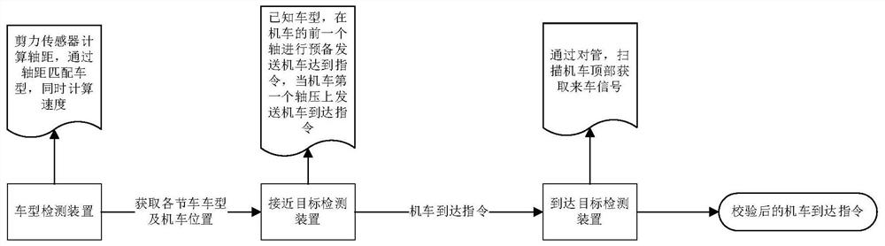
[0066] Based on the second embodiment, the present invention also proposes a method for judging the position of the locomotive in the train. Figure 8 It is a step diagram of the method for judging the locomotive position in the train according to the embodiment of the present application. Such as Figure 8 As shown, the method for determining the position of the locomotive includes the following steps: Step S810 The vehicle type detection device 10 collects the first signal containing wheelbase information between the front and rear wheels of the train when the train arrives at the first position, wherein the first position and the target position Preset the first distance at intervals; step S820 approaches the target detection device 20 and collects the second signal containing the information of the second position when the current train travels from the first position to the second position; step S830 the data processing device 30 receives the first signal and the second ...


PUM


Abstract

The invention discloses a system for judging the position of a locomotive in a train, comprising: a vehicle type detection device, which is arranged at a track at a first position, and is used to collect a first signal when the train passes the current position; an approaching target detection device, It is arranged at the second position track close to the target position, and is used for collecting the second signal when the train travels from the first position to the second position; a data processing device, which is used for determining the axis between adjacent wheels according to the first signal Then according to the second signal and combined with the position of the number of sections, when the first wheel of the locomotive to be identified passes the second position, an instruction for prompting the locomotive to be identified to reach the target position is generated . The invention can directly judge the position of the locomotive, has high reliability, low cost, is easy to implement in engineering, and realizes redundancy check of locomotive arrival instructions, and is applicable to various ground automatic over-phase separation devices.

Description

technical field [0001] The invention relates to the field of railway rail transit, in particular to a system and method for judging the position of a locomotive in a train. Background technique [0002] The electrified railway catenary adopts single-phase power frequency AC power supply mode. In order to reduce the voltage imbalance of the three-phase power supply network of the power system and improve the utilization rate of the power grid, the electrified railway adopts segmented and phase-separated power supply, that is, two power supplies with different voltage phases A section of non-electric neutral zone is embedded between the arms, and the transition between each powered arm and the neutral zone is smooth through anchor segment joints. In the operation of electrified railways, in order to reduce the adverse effects of the catenary electrical phase separation area, most of them use automatic phase separation on the vehicle or automatic phase separation on the ground....

Claims


Application Information

Patent Timeline
Patent Type & Authority Patents(China)
IPC IPC(8): B61L25/02B61L1/16
CPCB61L25/025B61L25/021B61L1/163
Inventor 何健明吴丽然胡前周方圆刘正雄刘永丽田哲孙茂吕顺凯仇乐兵邱文俊肖宇翔徐晓天李幼保郭积晶
Owner ZHUZHOU CSR TIMES ELECTRIC CO LTD
Why Eureka
Try Eureka