Fan module

A fan module and fan technology, which can be used in household refrigeration equipment, lighting and heating equipment, liquid fuel engines, etc., and can solve problems such as noise and flow loss

Inactive Publication Date: 2009-07-01
LG ELECTRONICS INC
View PDF0 Cites 6 Cited by
  • Summary
  • Abstract
  • Description
  • Claims
  • Application Information

AI Technical Summary

Problems solved by technology

This wire is located within the flow field generated by the axial fan, which causes flow resistance and thus noise and flow losses

Method used


Image

  • Fan module
  • Fan module
  • Fan module

Examples


Embodiment Construction

[0041] A fan module for a refrigerator according to non-limiting embodiments of the present invention is described in detail below with reference to the accompanying drawings. Although embodiments have been described herein, it should be understood that various other modifications and embodiments can be devised by those skilled in the art without departing from the spirit and scope of the principles of this invention.

[0042] A fan module according to a first non-limiting embodiment of the present invention will be described in detail below with reference to the accompanying drawings.

[0043] First, the configuration of a machine room of a refrigerator having a fan module according to this embodiment will be described.

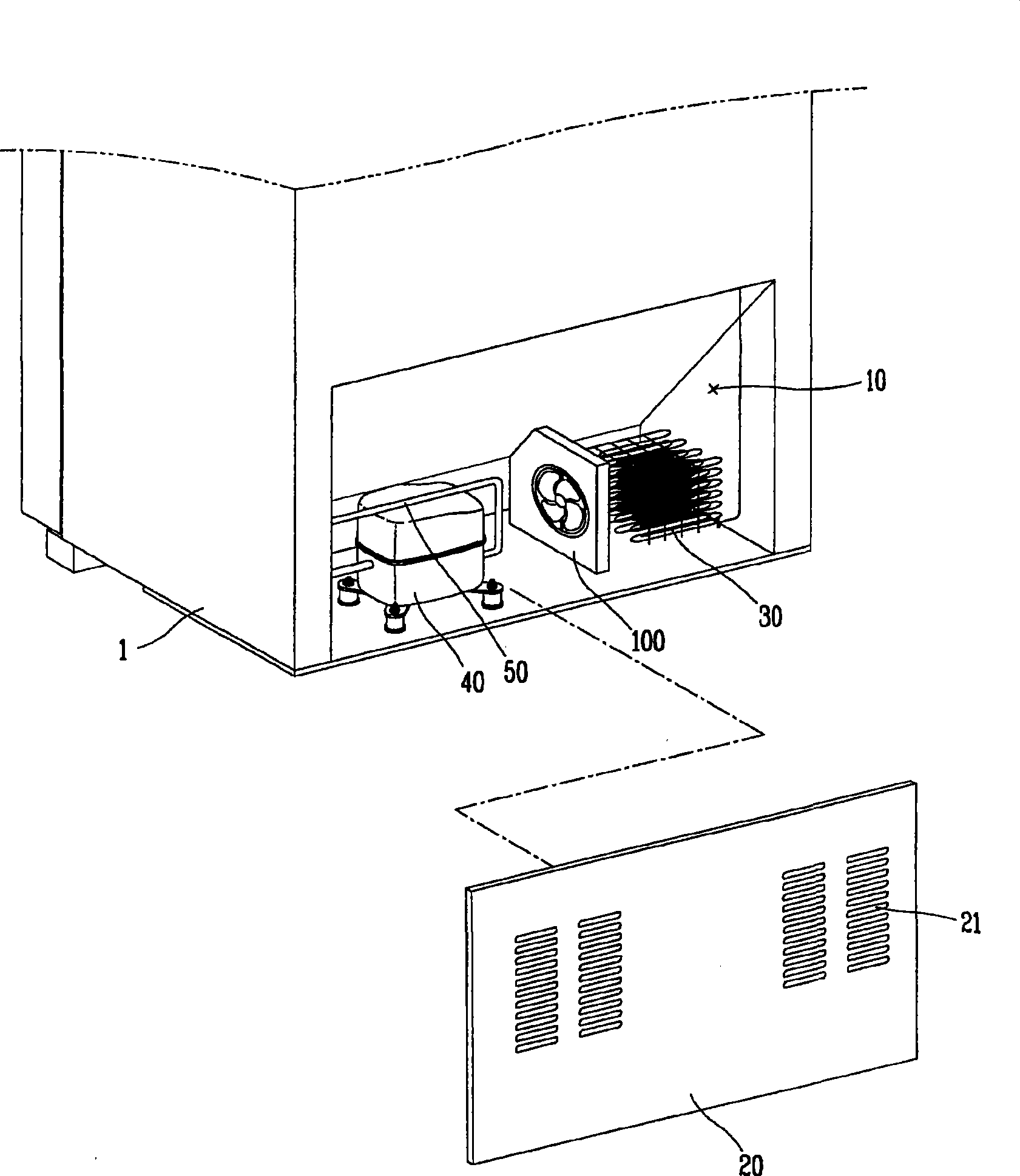
[0044] figure 1 is a schematic diagram showing a machine room of a refrigerator having a fan module according to a first non-limiting embodiment of the present invention.

[0045] refer to figure 1 , the mechanical room 10 of the refrigerator 1 includes a...


PUM


Abstract

A fan module is provided. The fan module is configured to dissipate heat from, e.g., a compressor and a condenser disposed in a machine room of the refrigerator. The fan module includes a fan, a shroud having a receiving hole positioned around the fan, a fan mounting portion coupled to a rear surface of the shroud on which the fan is mounted, the rear surface facing a downstream airflow direction of the fan, and a concave recess provided on a rear surface of the shroud and circling the receiving hole. The fan module prevents noise caused by air passing through the receiving hole and prevents flow loss.

Description

[0001] This application claims priority from Korean Application No. 10-2007-0136865 filed in Korea on December 24, 2007, the entire contents of which are hereby incorporated by reference. technical field [0002] The present invention relates to a fan module, in particular to a fan module capable of cooling a compressor and a condenser arranged in a machine room of a refrigerator. Background technique [0003] Refrigerators are generally used to store food in a frozen state or a refrigerated state using a low temperature according to the type of food to be stored. [0004] When the refrigerant performs a heat exchange operation, cool air supplied into the refrigerator is generated, and when the refrigerant repeatedly performs cycle operations such as compression-condensation-expansion-evaporation, the cool air is continuously supplied into the refrigerator. The cold air is uniformly delivered to the inside of the refrigerator by convection, and is used to preserve food in th...

Claims


Application Information

Patent Timeline
Patent Type & Authority Applications(China)
IPC IPC(8): F04D19/00F04D25/08
CPCF04D29/663F25D2323/00281F04D29/164F04D29/681F04D25/08F04D29/646F25D23/00F25D11/00F04D29/54
Inventor 刘明根申铉定
Owner LG ELECTRONICS INC
Why Eureka
Try Eureka