Structure for drawing out lead wires from a coil device

A technology of coil device and lead-out structure, which is applied to the parts, coils, valve devices and other directions of the connection device, can solve the problems of fracture and hidden dangers in strength, and achieve the effect of preventing the wire portion from breaking and maintaining the connection state.

Active Publication Date: 2009-07-01
FUJIKOKI MFG CO LTD
View PDF1 Cites 9 Cited by
  • Summary
  • Abstract
  • Description
  • Claims
  • Application Information

AI Technical Summary

Problems solved by technology

Therefore, there is a problem that after the wire portion 68a and the conductive pattern of the wiring board 67 are soldered, if a load is applied to the lead wire 68, the pre-soldered portion of the wire portion 68a may break, and there is a problem in terms of strength. Hidden danger

Method used


Image

  • Structure for drawing out lead wires from a coil device
  • Structure for drawing out lead wires from a coil device
  • Structure for drawing out lead wires from a coil device

Examples


Embodiment Construction

[0054] Embodiments of the present invention will be described below with reference to the drawings. In addition, in the following description, the present invention is applied to Figure 9 The electric valve shown is driven by the coil device 65 of the stepper motor used.

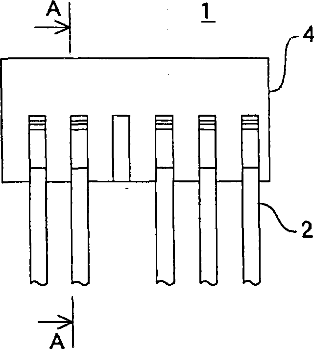
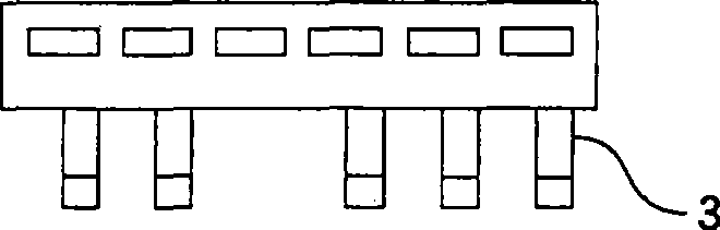
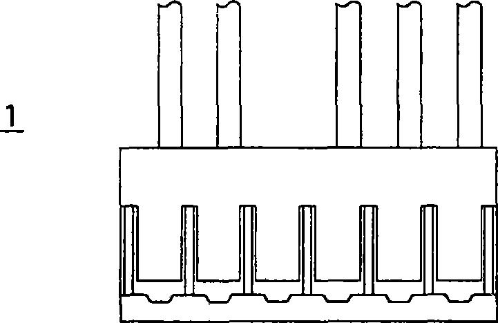
[0055] Figure 1(a)-Figure 1(e) It shows a connector constituting the lead-out structure of the coil device of the present invention. The connector 1 consists of a lead wire 2, a crimp terminal 3 mounted on the top end of the lead wire 2, and a housing that engages with the crimp terminal 3 and holds the lead wire 2. 4 constitute.

[0056] The crimp terminal 3 is formed of a thin metal plate such as Figure 2(a)-Figure 2(c)Shown includes: a wire holding portion 3a holding the wire portion 2a of the lead wire 2 (refer to FIG. 1 ); a covering holding portion 3b holding the covering portion 2b of the lead wire 2; protruding perpendicularly to the axial direction of the wire portion 2a of the lead wire 2 Pro...


PUM


Abstract

The present invention prevents an exposed conductor portion from breaking and to maintain connection state between lead wires and a wiring board even when a load is added to the lead wires under the condition that the lead wires for a coil device is connected to and retained on the wiring board. In a structure for drawing out lead wires from a coil device according to the present invention, for drawing a lead wire from a terminal pin of a coil device 65 having a coil 62 and a plurality of terminal pins to which ends of the coil are connected, an end of the lead wire 2 is connected to a connector 1, the connector is connected at a side face thereof to a wiring board 67 for relay, and the wiring board is connected to the terminal pin. A connection terminal of the connector is connected to the wiring board in a direction perpendicular to a direction that the lead wire extends. In another case, after an end of the lead wire is connected a crimp terminal 3, the crimp terminal is connected at a side face thereof to a wiring board for relay, and thereafter the wiring board is connected to the terminal pin.

Description

technical field [0001] The present invention relates to a lead wire drawing structure of a coil device used to energize a coil or the like wound on a bobbin of an electromagnetic coil. Background technique [0002] In the past, for example, the electric valve described in Patent Document 1 such as Figure 9 As shown, the coil device 65 of the stepper motor 60 used to drive the electric valve consists of a coil frame 61, a coil 62 wound on the coil frame 61, a terminal pin 63 connected to the end of the coil 62, and a terminal pin 63 left. The resin sealing part 64 which resin-seals the bobbin 61, the coil 62, and the terminal pin 63 at the front end part is comprised. When the lead wires are drawn out from the coil device 65, the driving IC and the like are disposed on the wiring substrate 67, the wire portion 68a of the lead wire 68 is inserted into the receiving hole of the wiring substrate 67, and soldered to the conductive pattern of the wiring substrate 67 by soldering....

Claims


Application Information

Patent Timeline
Patent Type & Authority Applications(China)
IPC IPC(8): H02K3/46
CPCH01F27/04H01R4/023H01R13/567H01R13/6658H01R2201/22H01F5/04H04R2209/041H01F7/06H04R9/046F16K31/04H01R12/75
Inventor 小柳津薰
Owner FUJIKOKI MFG CO LTD
Why Eureka
Try Eureka