Automatic intervention device of catheter
A catheter and automatic technology, applied in the direction of catheters, etc., can solve problems such as difficult force feedback, short motor life, and slippage, and achieve high precision, lower proficiency requirements, and high efficiency.
Inactive Publication Date: 2010-12-01
HARBIN INST OF TECH
View PDF0 Cites 0 Cited by
- Summary
- Abstract
- Description
- Claims
- Application Information
AI Technical Summary
Problems solved by technology
The purpose of the present invention is to solve the problems of difficult force feedback and slippage in the existing continuous conveying device, while the motor needs to be frequently alternated in positive and negative directions during the operation of the intermittent conveying device, the life of the motor is short, and the catheter cannot be replaced automatically. Automated Catheter Intervention Device
Method used
View moreImage
Smart ImageViewing Examples
Examples
specific Embodiment approach 1
specific Embodiment approach 2
specific Embodiment approach 3
Login to View More PUM
 Abstract
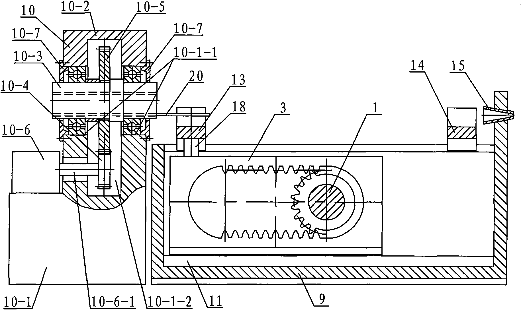
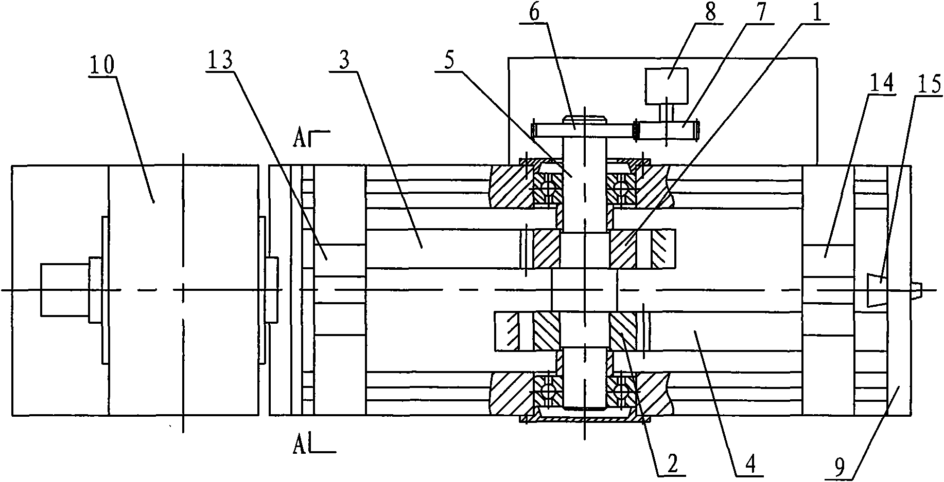
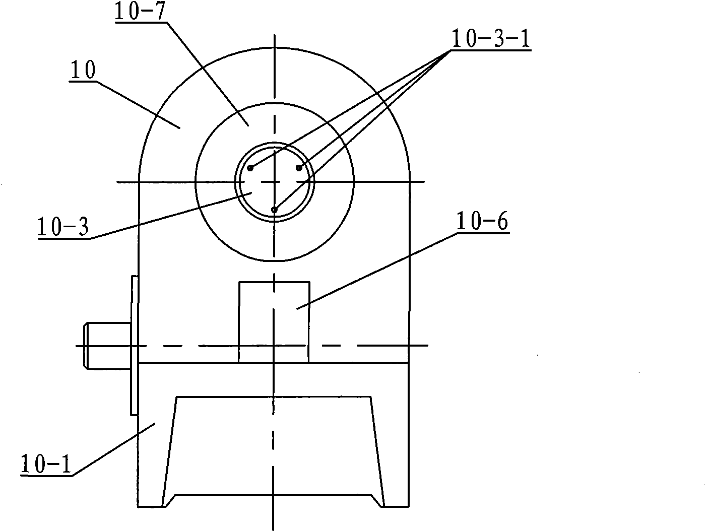
A conduit automatic intervention device relates to a conduit delivery mechanism. The conduit automatic intervention device solves the problems that the existing continuous mode delivery mechanism has difficult force feedback and has slippage; the motor of a batch-type delivery mechanism needs frequently positive inverted alternation. Two holding jaw fixed rails are symmetrically arranged on the outside of a first fixed rail and a second fixed rail. A dovetail at the lower end of a first double rack is matched with a dovetail groove of the first fixed rail. The dovetail at the lower end of a second double rack is matched with the dovetail groove of the second fixed tail. A first half gear and a second half gear are respectively arranged on a shaft, the two ends of which are articulated with the two holding jaw fixed rails. A first holding jaw mechanism is fixedly arranged on a first connection plate and a second holding jaw mechanism is fixedly arranged on a second connection plate. The centre line of a catheter sheath is superposed with the axle center of the first holding jaw mechanism and the second holding jaw mechanism. The axle center of a tunnel body of a tube replacing mechanism is superposed with the axle center of the first holding jaw mechanism and the second holding jaw mechanism. The conduit automatic intervention device realizes the continuous delivery of the conduit and avoids the frequency starting of the motor.
Description
A catheter automatic intervention device technical field The invention relates to a catheter delivery device, in particular to an interventional device used for automatic catheter delivery in minimally invasive interventional operations. Background technique Minimally invasive interventional surgery has been widely used in the world due to its advantages of less bleeding, less trauma, less complications, safety and reliability, and quick postoperative recovery. Catheter is the most important tool in interventional surgery. At present, catheter intervention is mainly delivered manually by doctors at the operation site. The disadvantages are: (1) The operation accuracy is not easy to grasp. Vibration will cause damage to human tissue; (2) Doctors will inevitably suffer radiation damage when operating on site. To avoid radiation, doctors need to wear heavy lead clothing. Therefore, the development trend of catheter intervention must be remote operation, that is, the doctor l...
Claims
Login to View More Application Information
Patent Timeline
 Patent Type & Authority Patents(China)
IPC IPC(8): A61M25/082
Inventor 付宜利刘浩黄文泰颜增翼王树国
Owner HARBIN INST OF TECH
Features
- R&D
- Intellectual Property
- Life Sciences
- Materials
- Tech Scout
- Unparalleled Data Quality
- Higher Quality Content
- 60% Fewer Hallucinations
Learn More Browse by: Latest US Patents, China's latest patents, Technical Efficacy Thesaurus, Application Domain, Technology Topic, Popular Technical Reports.
© 2025 PatSnap. All rights reserved.Legal|Privacy policy|Modern Slavery Act Transparency Statement|Sitemap|About US| Contact US: help@patsnap.com


