Temperature-regulating handle structure of constant-temperature tap

A technology for thermostatic faucets and handles, applied to valve operation/release devices, valve details, engine components, etc., can solve problems such as cumbersome operation, and achieve the effect of simple appearance and easy use

Inactive Publication Date: 2009-07-08
GUANGZHOU MOEN PLUMBING PRODS
View PDF0 Cites 9 Cited by
  • Summary
  • Abstract
  • Description
  • Claims
  • Application Information

AI Technical Summary

Problems solved by technology

This device is designed to prevent scalding. If you do not use buttons or dials when turning the handle to adjust the temperature, the temperature will not exceed the set temperature by 40° (there is also a setting of 38°), when a higher temperature is required When the

Method used


Image

  • Temperature-regulating handle structure of constant-temperature tap
  • Temperature-regulating handle structure of constant-temperature tap
  • Temperature-regulating handle structure of constant-temperature tap

Examples


Embodiment Construction

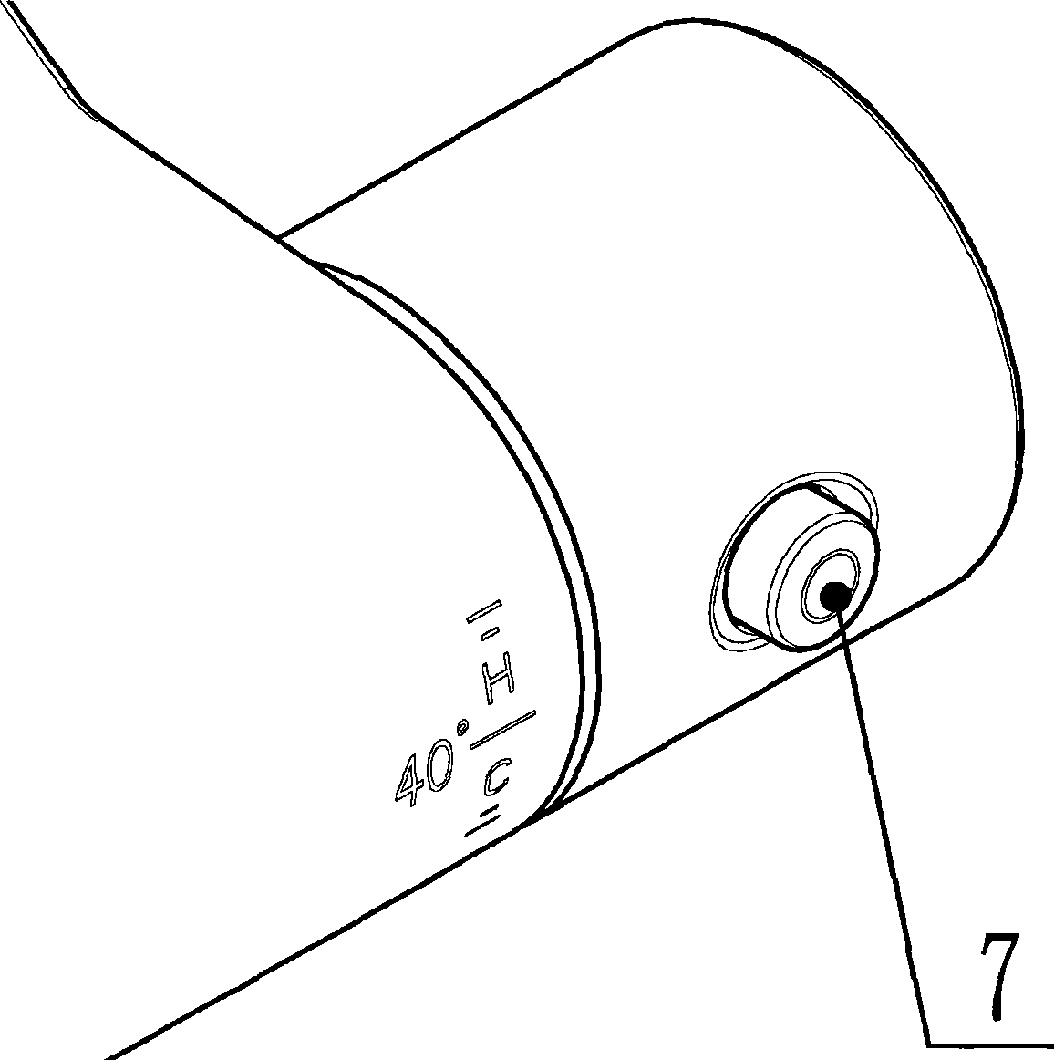
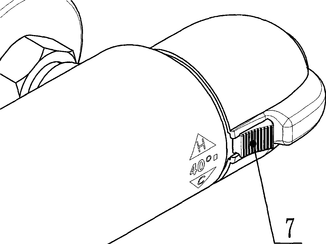
[0018] Such as figure 1 , figure 2 Shown: It is a schematic diagram of the structure of a traditional handle plus a button or a dial. 7 is a button or a dial. When the temperature needs to be adjusted, the button must be pressed or the dial is turned, and then the handle can be rotated to obtain the required temperature. This action Needs to act on two components, the handle and the button or toggle.

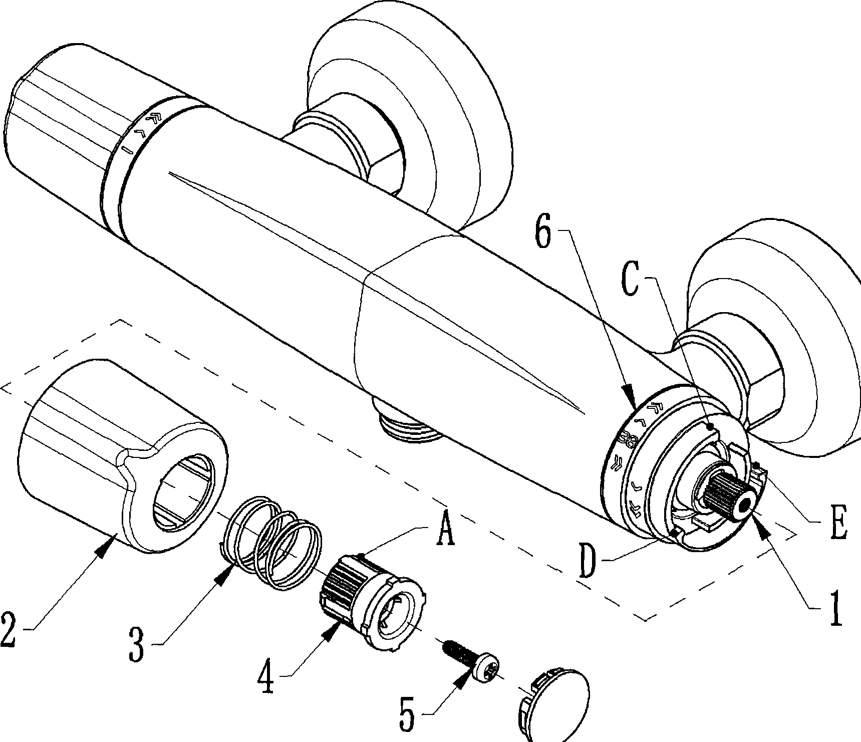
[0019] Such as image 3 As shown, the temperature adjustment handle structure includes: a thermostatic mandrel rod 1 , a handle 2 , a spring 3 , a joint 4 , a fixing screw 5 , and a stop ring 6 . The joint 4 is locked on the constant temperature mandrel rod 1 by the fixing screw 5, and the handle 2 and the joint 4 are matched through the gap between the key teeth, and the handle 2 can move horizontally on the key tooth A of the joint 4, and the handle 2 and the joint 4 are placed in the middle Spring 3. Three gears are set on the stop ring 6, which are the temperature upper...


PUM


Abstract

The invention discloses a thermoregulation handle structure of a constant temperature faucet, which is mainly comprises a faucet body, a constant temperature mandrel rod, a handle, a spring, a joint, a setscrew and a closing ring, wherein the constant temperature mandrel rod, the handle, the spring, the joint, the setscrew and the closing ring are arranged at one end of the faucet body. The handle and the joint are in clearance fit by a spline gear A, and the spring is arranged between the handle and the joint; the closing ring is provided with three shifts of an upper temperature limit shift D, a 38 DEG C shift C and a lower temperature limit shift E, and the three shifts form a thermoregulation and burn-proof structure; and a shift device B which rotates along the rotation of the handle is arranged on the corresponding handle. The invention changes that the prior handle can realize temperate regulation by adding a button or a toggle, and the handle with the structure can move along the axial direction of the constant temperature mandrel rod. Simultaneously, the handle is rotated, and the constant temperature mandrel rod is also rotated. The thermoregulation handle structure has convenient use because of only operating the handle instead of operating the button or the toggle. Simultaneously, the constant temperature faucet has the advantage of concise appearance. The thermoregulation handle structure can be widely applied to the faucet with thermostatic regulation.

Description

Technical field: [0001] The invention relates to plumbing equipment, in particular to a temperature-regulating handle structure of a thermostatic faucet. Background technique: [0002] At present, the structural features of the temperature adjustment handle of the traditional thermostatic faucet are all button-type or dial-type. figure 1 , figure 2 shown. This device is designed to prevent scalding. If you do not use buttons or dials when turning the handle to adjust the temperature, the temperature will not exceed the set temperature by 40° (there is also a setting of 38°), when a higher temperature is required At this time, you must press the button or turn the toggle, and then you can rotate the handle to obtain the required higher temperature. This action needs to act on two parts, namely the handle and the button (or toggle), and the operation is very cumbersome. Invention content: [0003] The purpose of the present invention is to provide a thermostatic faucet t...

Claims


Application Information

Patent Timeline
IPC IPC(8): F16K31/60F16K31/64
Inventor 夏鹏程易海江余红斌关植贵石文辉
Owner GUANGZHOU MOEN PLUMBING PRODS
Why Eureka
Try Eureka