
Test method and system for image sensor dynamic resolution

An image sensor and testing method technology, applied in image communication, television, electrical components, etc., can solve the problems of inability to guarantee the accuracy of the image sensor, easy to be affected by the surrounding environment and subjective factors, and achieve the effect of improving the accuracy

Active Publication Date: 2012-01-11
BRIGATES MICROELECTRONICS KUNSHAN
View PDF0 Cites 2 Cited by
  • Summary
  • Abstract
  • Description
  • Claims
  • Application Information

AI Technical Summary

Problems solved by technology

[0011] However, the problem is that the traditional test method is mainly aimed at testing the static performance of the image sensor, and for the dynamic performance of the image sensor (capturing dynamic images), it is often only measured by human eyes observing the image effect collected by the image sensor. , this test method of human eye observation is easily affected by the surrounding environment and subjective factors, so it cannot guarantee the accuracy of the dynamic performance test of the image sensor

Method used


Image

  • Test method and system for image sensor dynamic resolution
  • Test method and system for image sensor dynamic resolution
  • Test method and system for image sensor dynamic resolution

Examples


Embodiment 1

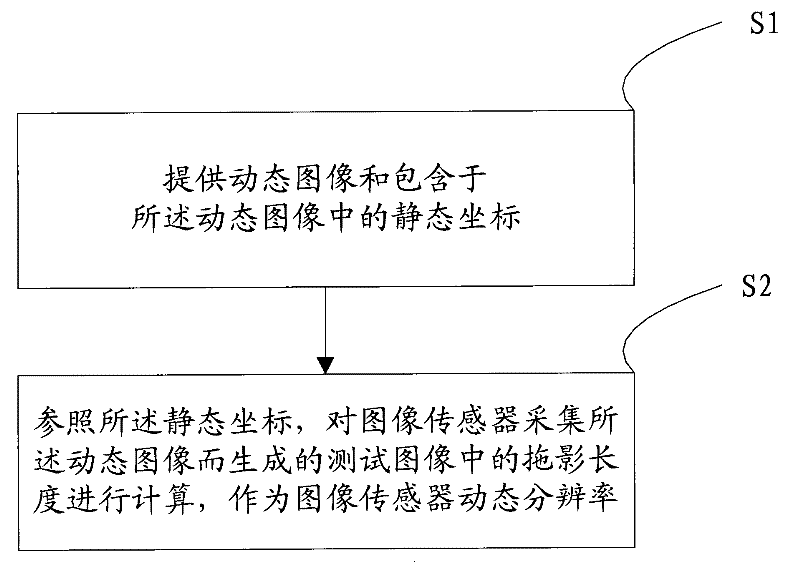
[0072] figure 1 It is a flow chart of the testing method for the dynamic resolution of the image sensor in this embodiment.

[0073] like figure 1 As shown, the test method of image sensor dynamic resolution includes:

[0074] First, referring to step S1, a dynamic image and static coordinates contained in the dynamic image are provided.

[0075] Specifically, the step S1 includes:

[0076] Step S11, setting the motion state of the static object used to form the dynamic image.

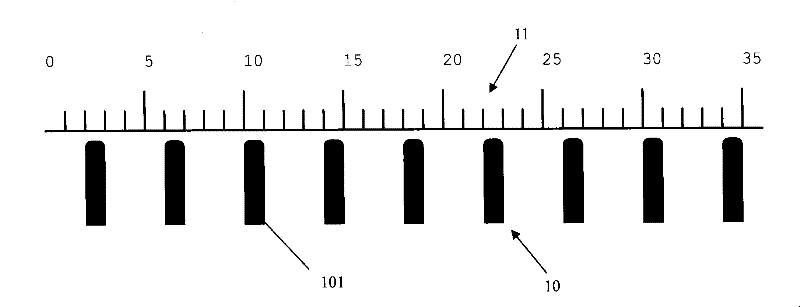
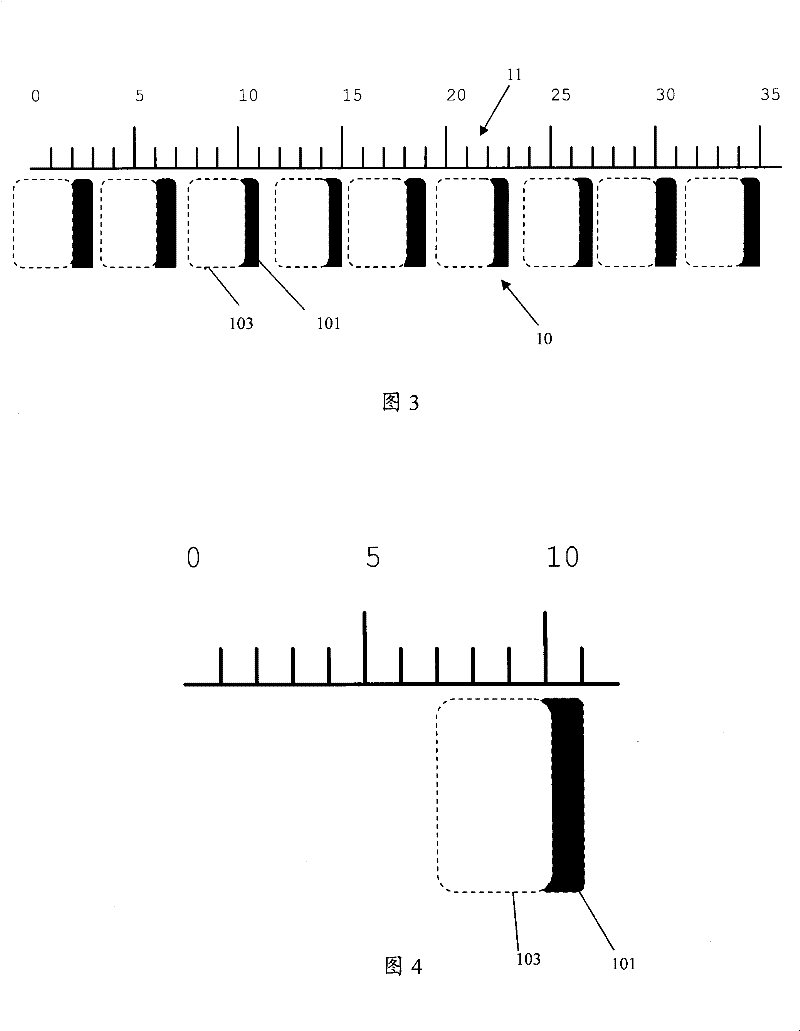
[0077] figure 2 It is a schematic diagram of a dynamic image in this embodiment, and only the initial frame of the dynamic image is shown in the figure. As shown in the figure, the black vertical bar column 10 composed of a series of black vertical bars 101 arranged in parallel in the horizontal direction with equal intervals and the same size is used as a static object, and the motion state of the static object is set, and the motion state includes the static object The direction, speed, accele...

Embodiment 2

[0103] Figure 7 It is a schematic diagram of the test system for the dynamic resolution of the image sensor in this embodiment.

[0104] As shown in the figure, the test system includes: a dynamic image providing device 30 and a test image processing device 40; wherein,

[0105] A dynamic image providing device 30, configured to provide a dynamic image and static coordinates contained in the dynamic image to the image sensor;

[0106] The test image processing device 40 is configured to refer to the static coordinates to calculate the smear length in the test image generated by the image sensor collecting the dynamic image as the dynamic resolution of the image sensor.

[0107] Specifically, the dynamic image providing device 30 includes: a dynamic image setting unit and a dynamic image output unit; wherein,

[0108] The dynamic image setting unit is used to set the motion state of the static object forming the dynamic image, and set the static coordinates corresponding to ...


PUM


Abstract

The present invention provides a method for testing dynamic resolution factor of image sensor and a system thereof, wherein the method comprises the following steps: providing dynamic image and dynamic coordinate in the dynamic image; and calculating the streaking length in the test image generated through collecting the dynamic image by the image sensor as the dynamic resolution factor of image sensor. The test method and system of the invention can measure the dynamic resolution factor of image sensor with a quantified mode for increasing the accuracy in detecting the dynamic performance of image sensor.

Description

technical field [0001] The invention relates to the technical field of image sensors, in particular to a method and system for testing the dynamic resolution of an image sensor. Background technique [0002] With the rapid development and wide application of technologies such as digital photography, network video, and image acquisition, the image sensor, which is a key photoelectric component in the above-mentioned technologies and used to realize image signal acquisition, has been focused on by the industry, and a lot of research and development efforts have been invested. [0003] Based on product category, currently image sensors are mainly divided into Charge Coupled Device (CCD) image sensors, Metal Oxide Semiconductor (Complementary Metal-Oxide Semiconductor, CMOS) image sensors and Contact Image Sensors (Contact Image Sensor, CIS) three kinds. CCD image sensors are generally used in high-end technology for camera and photography, while CMOS image sensors are used in ...

Claims


Application Information

Patent Timeline
Patent Type & Authority Patents(China)
IPC IPC(8): H04N17/00
Inventor 潘徐君池国泉曹庆红
Owner BRIGATES MICROELECTRONICS KUNSHAN
Learn More