A kind of prefabricated hollow composite beam and the cast-in-place construction method of beam and prefabricated slab

A technology of prefabricated slabs and superimposed beams, applied in joists, girders, trusses, etc., can solve the problems of easy oxidation of metal materials of joints, large amount of steel used for joints of beams, structural limitations of beam heights, etc., so as to facilitate the reduction of concrete , The effect of improving strength and improving load capacity

Inactive Publication Date: 2011-12-14
刘馨裕
View PDF0 Cites 0 Cited by
  • Summary
  • Abstract
  • Description
  • Claims
  • Application Information

AI Technical Summary

Problems solved by technology

[0003] The first purpose of the present invention is to provide a prefabricated hollow composite beam for the defects and deficiencies of the existing beam members, such as large ineffective dead weight, beam height limited by the structure, and difficult to increase.
[0004] The second purpose of the present invention is to provide a prefabricated hollow composite beam and prefabricated slab for the defects and deficiencies of the existing beam and slab construction method, such as time-consuming material consumption, large amount of steel used for beam body joints, and easy oxidation of joint metal materials. Pouring construction method

Method used


Image

  • A kind of prefabricated hollow composite beam and the cast-in-place construction method of beam and prefabricated slab
  • A kind of prefabricated hollow composite beam and the cast-in-place construction method of beam and prefabricated slab
  • A kind of prefabricated hollow composite beam and the cast-in-place construction method of beam and prefabricated slab

Examples


Embodiment Construction

[0025] The present invention will be described in further detail below in conjunction with accompanying drawing description and specific embodiment:

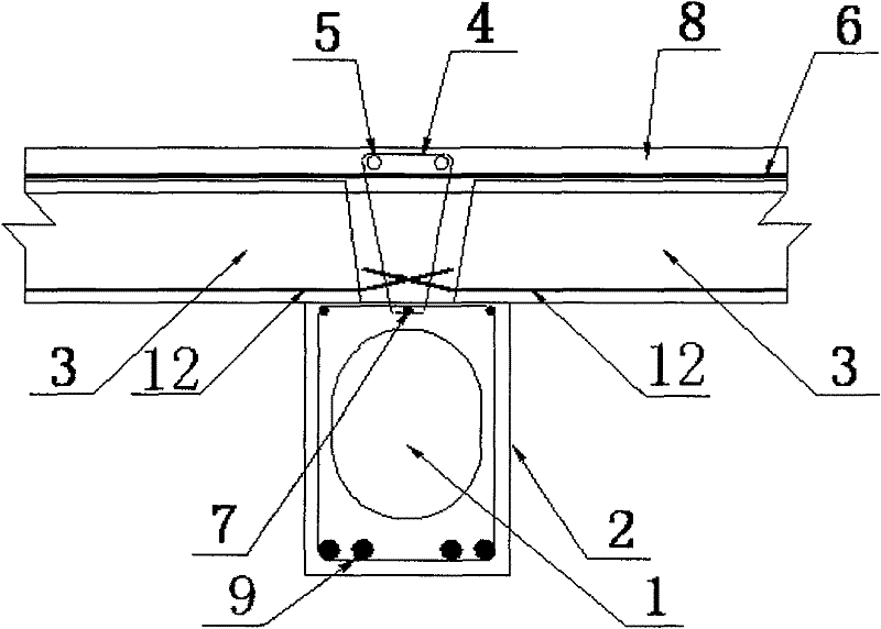
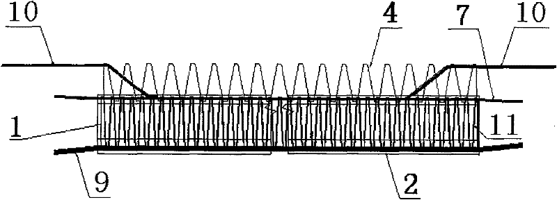
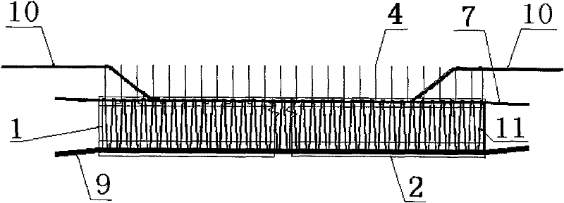
[0026] see figure 1 , figure 2 , image 3 , a prefabricated hollow composite beam of the present invention, which is prefabricated by steel bars and concrete, a through hole 1 is provided in the center of the section of the beam body 2, and a Vertical fibers 4 connected by ribs 7 .

[0027] The through hole 1 is a round hole or a waist circular hole arranged along the height direction of the beam body 2, so as to reduce the physical space of the neutral axis of the beam body 2 as much as possible, and the cross-sectional area of ​​the through hole 1 is generally 1 / 3-2 / 3 of the cross-sectional area of ​​body 2. The through hole 1 on the beam body 2 can reduce the self-weight to the greatest extent so as to improve the load capacity and reduce the proportion of invalid materials.

[0028] Such as figure 1 , image 3 As sho...


PUM


Abstract

A prefabricated hollow composite beam and a cast-in-place construction method of the beam and the prefabricated slab. Belonging to the technical field of building components, a through hole (1) is provided in the center of the cross-section of the beam body (2), and the upper part of the beam body (2) is provided with a vertical rib (7) connected to the inside of the beam body (2). Vertical fibers (4). A. Place the prefabricated slabs (3) on both sides of the upper plane of the beam body (2), and reserve pouring joints between the prefabricated slabs (3) and the vertical fibers (4); B. To the beam body (4) Concrete is poured at the butt joints of the prefabricated slabs (3) until the vertical fibers (4) are buried, or concrete is poured integrally above the beam body (2) and the prefabricated slab (3), vibrated, smoothed, cured and solidified, that is, into cast-in-place beam slabs. The self-weight of the beam body (2) is reduced, and the superposition effect is generated by the vertical fibers, so that the height of the beam is greatly increased, and the internal space of the building structure is not occupied, so it is suitable for building buildings with a frame structure and also suitable for high-rise buildings.

Description

technical field [0001] The invention relates to a construction method of prefabricated beams and beam-slab components, in particular to a prefabricated hollow composite beam and a cast-in-place construction method of beams and prefabricated slabs. The utility model belongs to the technical field of concrete prefabricated components and building construction. Background technique [0002] At present, with the continuous improvement of people's living standards, home decoration is also increasingly emphasizing personalized redesign, high-end and luxury. Adapting to this, the structural form of the house is also based on the frame structure that creates flexible and variable elastic space. as the subject. The main forms of frame structure are cast-in-place reinforced concrete frame structure and assembled frame structure, among which the assembled frame structure is mostly steel structure. Because the joints of assembled concrete structural members mostly adopt the "steel sto...

Claims


Application Information

Patent Timeline
Patent Type & Authority Patents(China)
IPC IPC(8): E04B5/04E04C3/20
Inventor 刘馨裕
Owner 刘馨裕
Why Eureka
Try Eureka