
Handheld rotary cutter

A rotary cutting and rotary ground technology, applied in metal processing and other directions, can solve problems affecting user comfort, strain or other diseases, and achieve the effect of improving ergonomic design and increasing comfort

Inactive Publication Date: 2009-07-22
OY FISKARS AB
View PDF3 Cites 5 Cited by
  • Summary
  • Abstract
  • Description
  • Claims
  • Application Information

AI Technical Summary

Problems solved by technology

This arrangement greatly affects the comfort of the user and in the long run can cause strain or other ailments

Method used


Image

  • Handheld rotary cutter
  • Handheld rotary cutter
  • Handheld rotary cutter

Examples


Embodiment Construction

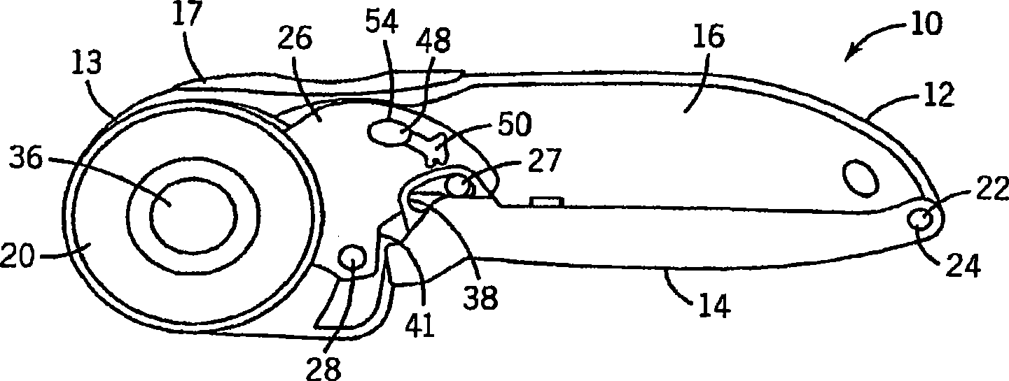
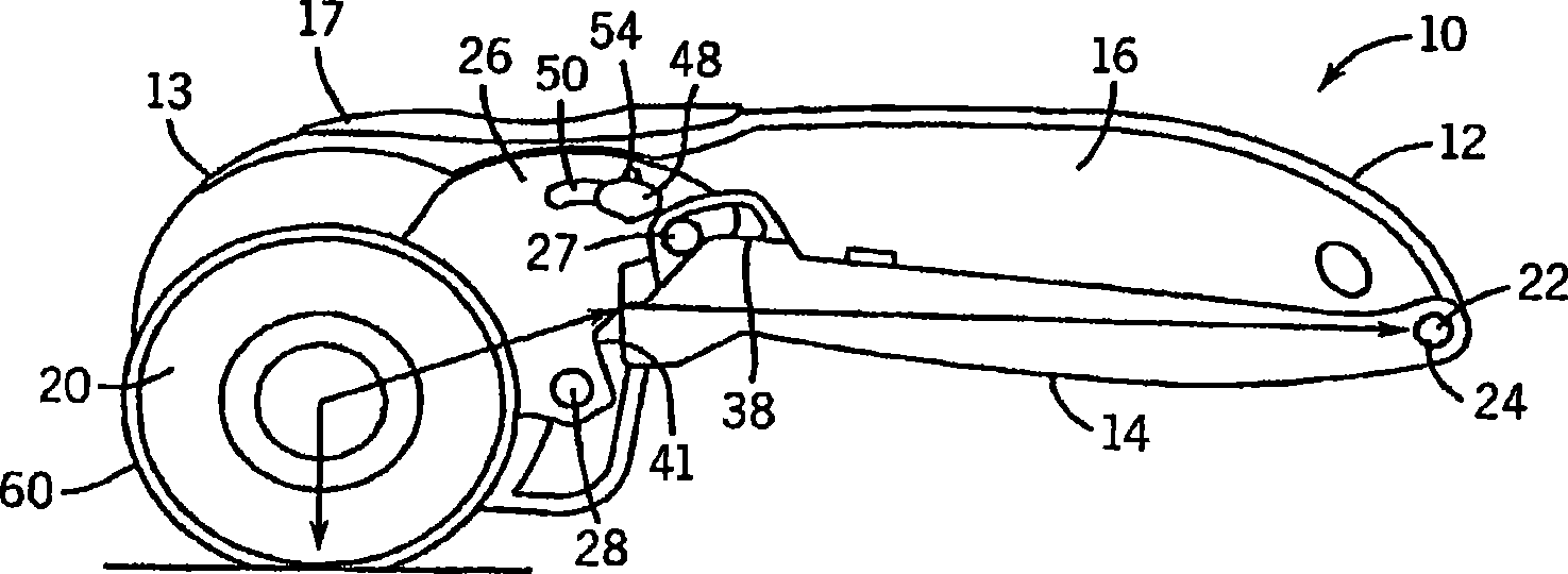
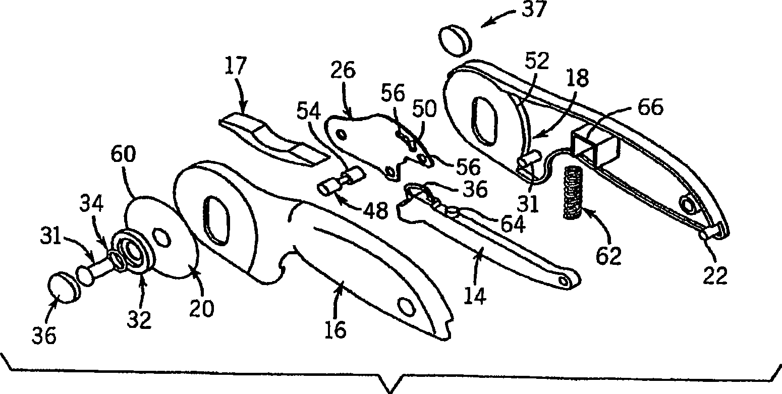
[0016] Figures 1 to 3 A rotary cutter 10 constructed in accordance with the principles of the present invention is shown. The rotary cutter 10 includes a body 12 having a cylindrical head 13 . Body 12 may take various forms. For example, body 12 may include separable but substantially identical right handle 16 and left handle 18 that may be disposed around blade 20 or both disposed on one side of blade 20 and partially connected by handle insert 17 . Those skilled in the art will also appreciate that other arrangements and configurations of the body 12 are possible.

[0017] Trigger 14 is rotatably coupled to body 12 at rear pivot point 22 . in such as Figures 1 to 3 In the embodiment shown, this is accomplished by coupling the trigger 14 to the body 12 using a plastic or metal rear pivot pin 24 .

[0018] In addition to the trigger 14 , a blade actuator 26 is also rotatably coupled to the body 12 . Such as figure 1 and 2 As shown, in various embodiments of the inven...


PUM


Abstract

A rotary cutter, comprising a body, a trigger and an actuator member. The body includes a rear end and a forward end, the forward end including a cylindrical head. The trigger is rotatably connected at one end thereof to the rear end of the body, and the actuator member is also rotatably connected to the body. The actuator member is in at least selective contact with the trigger such that rotation of the trigger results in a reciprocal rotation of the actuator member. A blade assembly is removably coupled to the actuator member and is configured to move between a retracted position and an extended position. Actuation of the trigger results in the blade assembly moving towards the extended position. When the blade assembly is in the extended position, the blade assembly is capable of contacting a cutting surface.

Description

[0001] Cross References to Related Applications [0002] This application claims priority to US Patent Application Serial No. 11 / 486,260, filed July 13,2006. technical field [0003] The present invention generally relates to a rotary cutter. More particularly, the present invention relates to hand-held rotary cutters for cutting materials such as fabric, cardboard, paper or other materials. Background technique [0004] The purpose of this section is to provide a background or context of the invention that is described in the claims. The description herein may include concepts that may be pursued, but not necessarily concepts that have been previously conceived or pursued. Therefore, unless otherwise indicated herein, what is described in this section is not prior art to the description and claims in this application and is not admitted to be prior art by inclusion in this section. [0005] Handheld rotary cutters are commonly used to cut layers of fabric, cardboard, pap...

Claims


Application Information

Patent Timeline
Patent Type & Authority Applications(China)
IPC IPC(8): B26B25/00
CPCB26B25/005
Inventor D·C·伊比L·拉姆J·C·博达R·斯科菲尔德C·达斯克
Owner OY FISKARS AB
Learn More