Charger

A charger and a technology to be charged, which is applied in secondary battery charging/discharging, secondary battery repair/maintenance, etc., can solve problems such as inability to share chargers, and achieve the effect of saving social resources and being convenient to use

Inactive Publication Date: 2009-07-29
麦广树
View PDF1 Cites 3 Cited by
  • Summary
  • Abstract
  • Description
  • Claims
  • Application Information

AI Technical Summary

Problems solved by technology

[0004] The purpose of the present invention is to solve the problem that different products to be charged cannot share the charger existing in the existing charger, and to provide an easy-to-use charger for digital products, so that most different types of products to be charged can be connected to each other. The same charger can be shared, and the product to be charged can be conveniently placed in the charger

Method used


Image

  • Charger
  • Charger
  • Charger

Examples


Embodiment 1

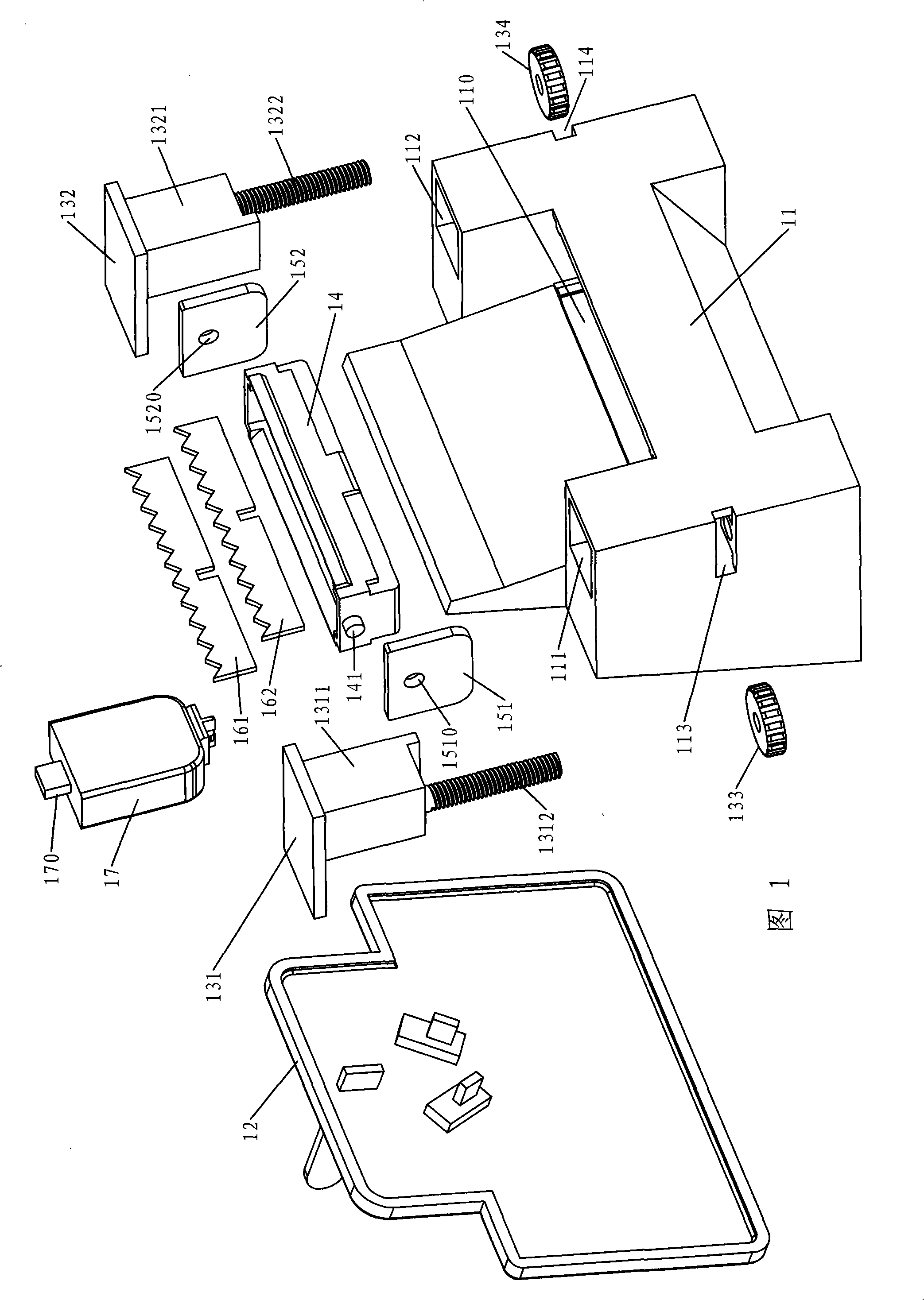
[0061] Embodiment 1, see FIG. 1 , which is a three-dimensional exploded view of a specific embodiment of the charger according to the present invention, which includes a charging circuit and a casing. (not shown on the figure), the circuit board is fixed in the inner cavity of the housing, and the power supply pin is fixed on the back of the bottom case 12 and extends horizontally (the charger in this embodiment is directly inserted into the power socket on the wall) type charger), there are guide cavities 111 and 112 on both sides of the face shell 11 to slide and match with the guide segments 1311 and 1321 on the limit blocks 131 and 132 respectively, and the dials 133 and 134 are put into the gaps 113 and 114 of the face shell respectively. The screw rods 1312 and 1322 on the lower parts of the limit blocks 131 and 132 are threadedly coupled in the inside, the charging plug 170 on the upper end of the adapter 17 is matched with the product to be charged—the charging jack on ...

Embodiment 2

[0071] Embodiment 2, change the surface shell structure in Figure 1 to the structure shown in Figure 11 and match the limit block shown in Figure 12 or Figure 13, and change the shape of the bottom shell to follow the surface shell accordingly.

[0072] As shown in Fig. 11, two circular limit jacks 211 and 212 are provided on the upper part of the front side of the face shell 21 to match the limit block shown in Fig. Two columns of square adjustment jacks 213 and 214 are arranged on the two sides respectively, wherein a single adjustment jack 213 and 214 is matched with the foot of the limit block shown in FIG.

[0073] See Figure 14, which is a schematic diagram of the use state of the second embodiment. The effect of the stoppers 221 and 222 is equivalent to the effect of the stoppers 132 and 131 in Figure 9, when the stoppers 221 and 222 in Figure 14 are inserted into the adjustment jacks 213 and 214 at different height positions, they can The length of the conversion head...

Embodiment 3

[0077] Embodiment 3, see Fig. 24, this embodiment is applicable to the mobile phone whose charging jack is located at the bottom side, the structure of the adapter 67 is the same as the adapter in Embodiment 1, and the structure of the pendulum 64, the electrode sheets 661 and 662 is also the same as that of the first embodiment. The same as in Embodiment 1, wherein the front shell 61 will combine the face shell and the limiting block according to the present invention into one - the limiting block and the front wall of the face shell enclose an accommodating cavity with an opening upward 610, the front wall, left wall, right wall, and lower wall of the front shell 61 are the stoppers, and the rear wall of the front shell 61 serves as the front shell to cover the bottom shell 62 to enclose the inner cavity of the shell , that is, the shell is composed of a bottom shell 62 and a front shell 61, and three power supply pins 631 (one of which is a ground pin, and there may be no el...


PUM


Abstract

The invention relates to a charger for digital products with convenient use. With such charger, most products with different model numbers to be charged can share one charger and can be put in the charger conveniently. The charger comprises a charging circuit, a shell, a converter which is provided with two wafers at the lower end and a charging plug at the upper end, an electrode plate which is provided with a positive output electrode and a negative output electrode on a swaying block pivot-jointed in the shell and a stop block extending frontwards in the front of the shell. When in use, the converter is plugged in the products waiting for being charged and then is arranged on the shell together; the products waiting for being charged can be fixed in the shell through using the swaying block, the stop block, the shell or the power socket or the wall; and the two wafers of the converter can firmly contact with the two electrode plates on the swaying block under the action of gravity, thus realizing the charging of the products waiting for being charged.

Description

technical field [0001] The invention relates to a charger, in particular to a charger for charging digital products such as mobile phones, MP3, MP4 or digital cameras. Background technique [0002] In the Chinese patent announcement CN2403133Y published on October 25, 2000, a "wall plug-in mobile phone charger" is disclosed, which mainly includes an insertion slot on the top and a plug on one side of the wall, wherein the plug The slot is concave, and the inside can be used for charging or discharging a mobile phone or a battery. The plug protrudes from one side of the wall, and an electronic circuit is arranged inside the charger body; the charger plug It can be positioned and used by directly plugging into the socket on the wall, eliminating the trouble and inconvenience of extending the wires of the known charger. Although this kind of charger can avoid the trouble of the charging line, its disadvantage is that the concave insertion slot corresponds to the mobile phone m...

Claims


Application Information

Patent Timeline
IPC IPC(8): H01M10/44
CPCY02E60/12Y02E60/10
Inventor 麦广树
Owner 麦广树
Why Eureka
Try Eureka