Voltage regulator

A voltage regulator and voltage regulation technology, applied in the direction of regulating electrical variables, control/regulating systems, instruments, etc., can solve the problem of unstable output current Iout

Inactive Publication Date: 2009-07-29
SEIKO INSTR INC
View PDF1 Cites 7 Cited by
  • Summary
  • Abstract
  • Description
  • Claims
  • Application Information

AI Technical Summary

Problems solved by technology

[0008] However, when the output voltage Vout is close to the detection voltage value due to the short circuit of the output terminal, the overcurrent protection circuit 75 performs the second limiting operation or releases the second limiting operation on the output current Iout based on one detection voltage value, so the output terminal is short-circuited. When the output current Iout is unstable
At this time, there is a danger that the output current Iout does not become the short-circuit current value but becomes an unexpected current value, causing the output voltage Vout to become 0V.

Method used


Image

  • Voltage regulator
  • Voltage regulator
  • Voltage regulator

Examples


Embodiment Construction

[0018] Embodiments of the present invention will be described below with reference to the drawings.

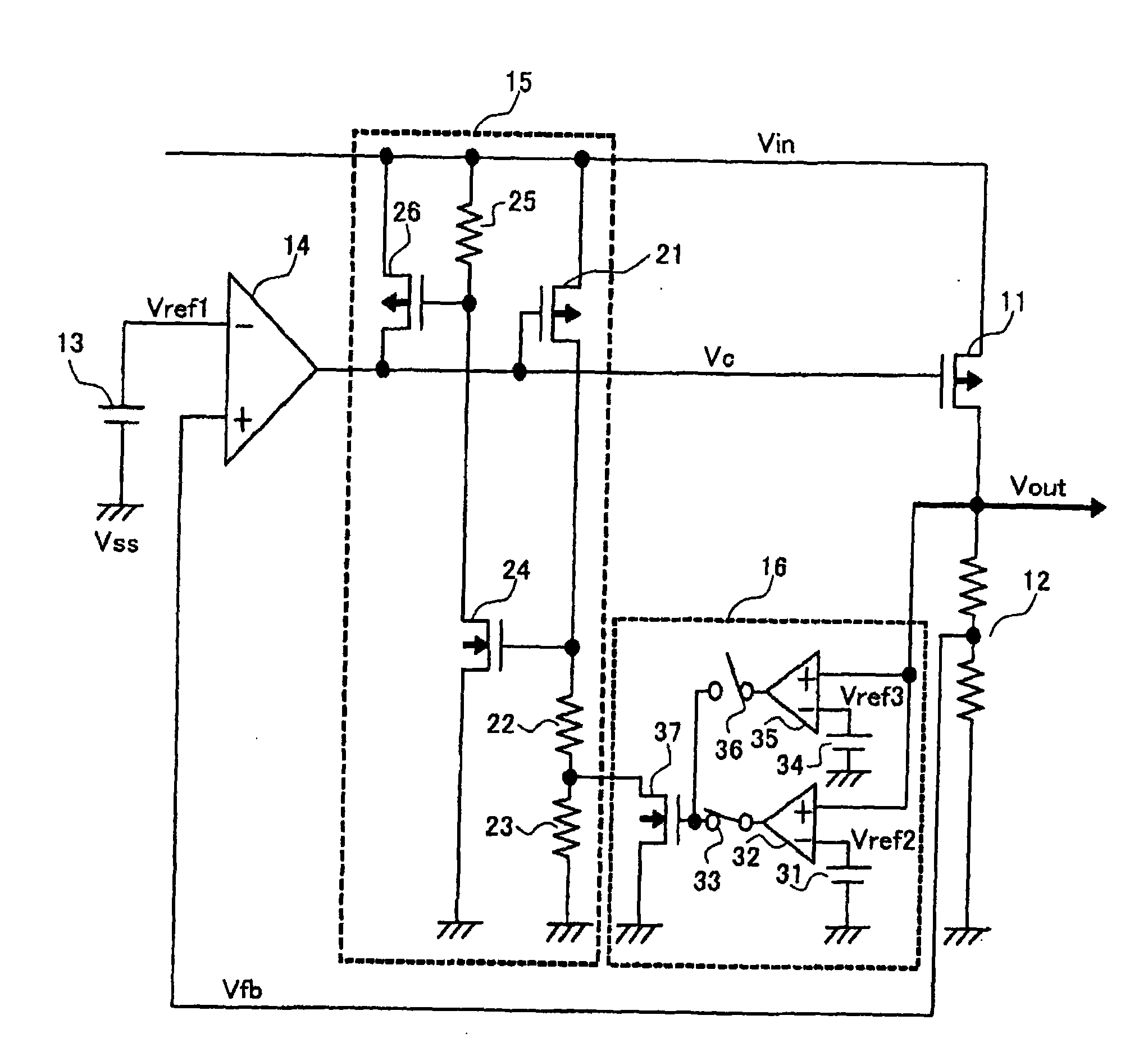
[0019] First, the configuration of the voltage regulator will be described. figure 1 is a circuit diagram showing the voltage regulator of the present invention.

[0020] The voltage regulator of the present invention has an output transistor 11 , a voltage dividing circuit 12 , a reference voltage circuit 13 , an amplifier circuit 14 , an overcurrent protection circuit 15 and a voltage detection circuit 16 . Overcurrent protection circuit 15 has PMOS 21 , resistors 22 to 23 , NMOS 24 , resistor 25 , and PMOS 26 . The voltage detection circuit 16 has a reference voltage circuit 31 , a comparison circuit 32 , a switch 33 , a reference voltage circuit 34 , a comparison circuit 35 , a switch 36 , and an NMOS 37 .

[0021] The gate of the output transistor 11 is connected to the output terminal of the amplifier circuit 14, the gate of the PMOS 21, and the drain of the PMOS 26, ...


PUM


Abstract

Provided is a voltage regulator capable of reducing fluctuation of an output current even when an output terminal thereof is short-circuited. In a case where the output terminal of the voltage regulator is short-circuited, an output current (Iout) of the voltage regulator is limited and fixed to a limit current value. When an output voltage (Vout) of the voltage regulator decreases to have a value equal to or smaller than not a detection voltage value (Vref3) of a reference voltage circuit (34) but a detection voltage value (Vref2) of a reference voltage circuit (31), a second limit operation in which the output voltage (Iout) is further limited to be decreased is set. Further, in a case where the output terminal is short-circuited and then reset, when the output voltage (Vout) has a value equal to or larger than not the detection voltage value (Vref2) but the detection voltage value (Vref3), the second limit operation is canceled.

Description

technical field [0001] The present invention relates to voltage regulators. Background technique [0002] First, a conventional voltage regulator will be described. image 3 is a circuit diagram showing a conventional voltage regulator. Figure 4 It is a graph showing the output voltage with respect to the output current of the conventional voltage regulator. [0003] Here, the output transistor 71 outputs the output voltage Vout according to the input voltage Vin and the control voltage Vc of the amplifier circuit 74 . When the output voltage Vout of the voltage regulator decreases, the output voltage Vout is divided by the voltage dividing circuit 72, and the divided voltage Vfb output by the voltage dividing circuit 72 also decreases. The divided voltage Vfb is compared with the reference voltage Vref1 generated by the reference voltage circuit 73 by the amplifying circuit 74, and when the divided voltage Vfb is smaller than the reference voltage Vref1, the control volt...

Claims


Application Information

Patent Timeline
Patent Type & Authority Applications(China)
IPC IPC(8): H02M3/137H02H3/08
CPCG05F1/573G05F1/56H02M3/155
Inventor 铃木照夫
Owner SEIKO INSTR INC
Why Eureka
Try Eureka