Shaft seal packing and shaft seal structure for valve
What is AI technical title?
AI technical title is built by PatSnap AI team. It summarizes the technical point description of the patent document.
A gasket and shaft seal technology, which is applied in the field of valve shaft seal structure, can solve the problems of disappearance of gap S, difficulty in obtaining self-sealing, limited tightening effect, etc., and achieve the effect of improving sealing performance
Active Publication Date: 2009-07-29
KITZ CORP
View PDF1 Cites 12 Cited by
Summary
Abstract
Description
Claims
Application Information
AI Technical Summary
This helps you quickly interpret patents by identifying the three key elements:
Problems solved by technology
Method used
Benefits of technology
Problems solved by technology
[0020] However, if the bolt-nut body 2 is tightened excessively, as shown in FIG. 19(c), the gap S between the laminated rings 8 becomes narrow, and the gap S may disappear.
In this way, the conventional annular liner 3 is provided with a gap S between the liners on the inner and outer peripheral sides, and it is deformed to fill the gap S during tightening, so the tightening effect is limited. In addition, the height The dimensional change in the direction is also large, so it is difficult to restore the sealing surface pressure with the stem part 4 and the gasket storage chamber 5.
In addition, there are very few parts of the annular gasket 3 subjected to fluid pressure, so it is difficult to exert the pressure of the edge 3b. 1 、6a 1 The lip effect also creates the problem that it is difficult to obtain self-sealing
Method used
Image
Click on the blue label to locate the original text in one second.
Reading with bidirectional positioning of images and text.
Examples
Embodiment 1
[0203] In order to set the peak side angle θ of the shaft seal gasket of the present invention 1 , and valley side angle θ 2 , the test of the sealing face pressure of the gasket body using different cone angles was carried out.
[0204] The valve of the test product is a 10K stainless steel suspension ball valve with a size of 50A. In addition, the shaft seal gasket has a structure in which 5 rings are laminated, and is made of PTFE (inner diameter φ22mm x outer diameter φ30mm x height 13.5mm), and has a symmetrical V-shaped cross section.
[0205] If the ring width of the main body of the gasket is W, and the height (sealing height) of the vertical surface connecting the upper lamination surface 16 and the lower lamination surface 17 is t, then there is a relationship of t=0.45W, and the sealing air of the bolt and nut can be measured. The minimum tightening torque at a pressure of 0.6MPa is measured for the sealing surface pressure.
[0206] For each test product, the an...
Embodiment 2
[0213] Next, a stress relaxation test was performed on the shaft seal gasket of the present invention.
[0214] As the test valve, the nominal pressure is 10K, the size of the ball valve is 50A, and the material of the ball valve body is SCS13A.
[0215] The size of the shaft seal gasket is φ22(mm)×φ32(mm)×11.5(mm) when the inner diameter×outer diameter×integrated together. Pad body in image 3 Make peak side angle θ 1 is 48°, so that the valley side angle θ 2 39°, in a state where two of the gasket main bodies are overlapped, the top adapter and the bottom adapter corresponding thereto are vertically attached.
[0216] On the other hand, as a comparative example, such as Figure 16 As shown, the peak side taper angle α'=(95 / 2)=47.5° of the gasket main body 101 is set, and the valley side taper angle β'=(90 / 2)=45° is set. In the same state (not shown), the upper adapter 102 and the lower adapter 103 corresponding thereto are installed up and down to form the V-shaped pack...
PUM
Abstract
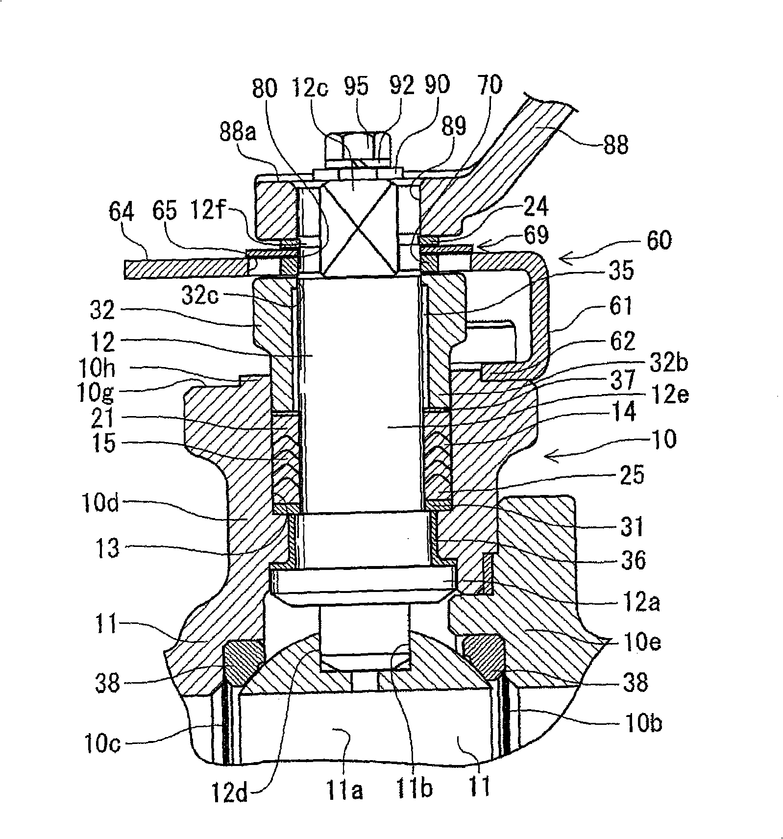
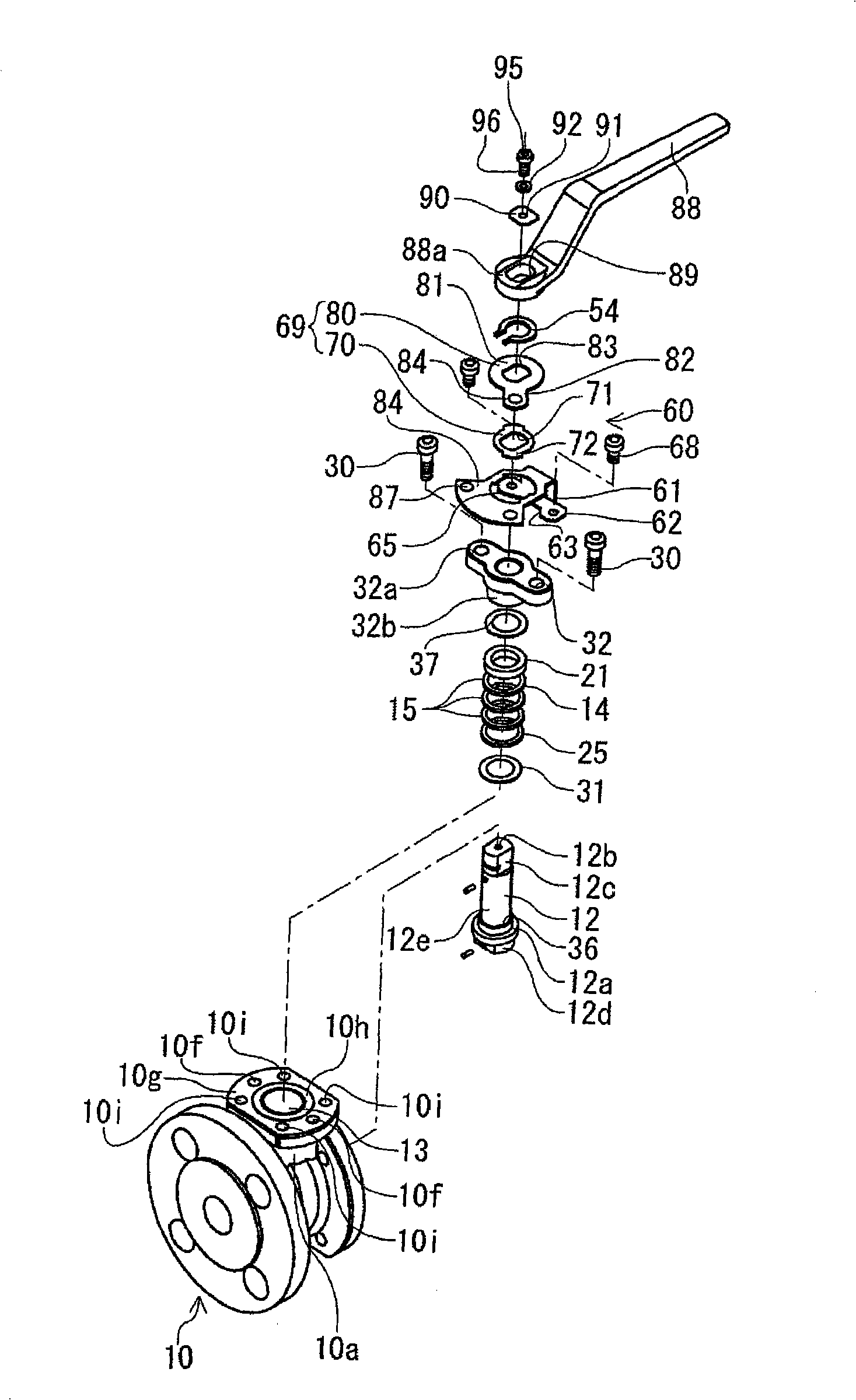
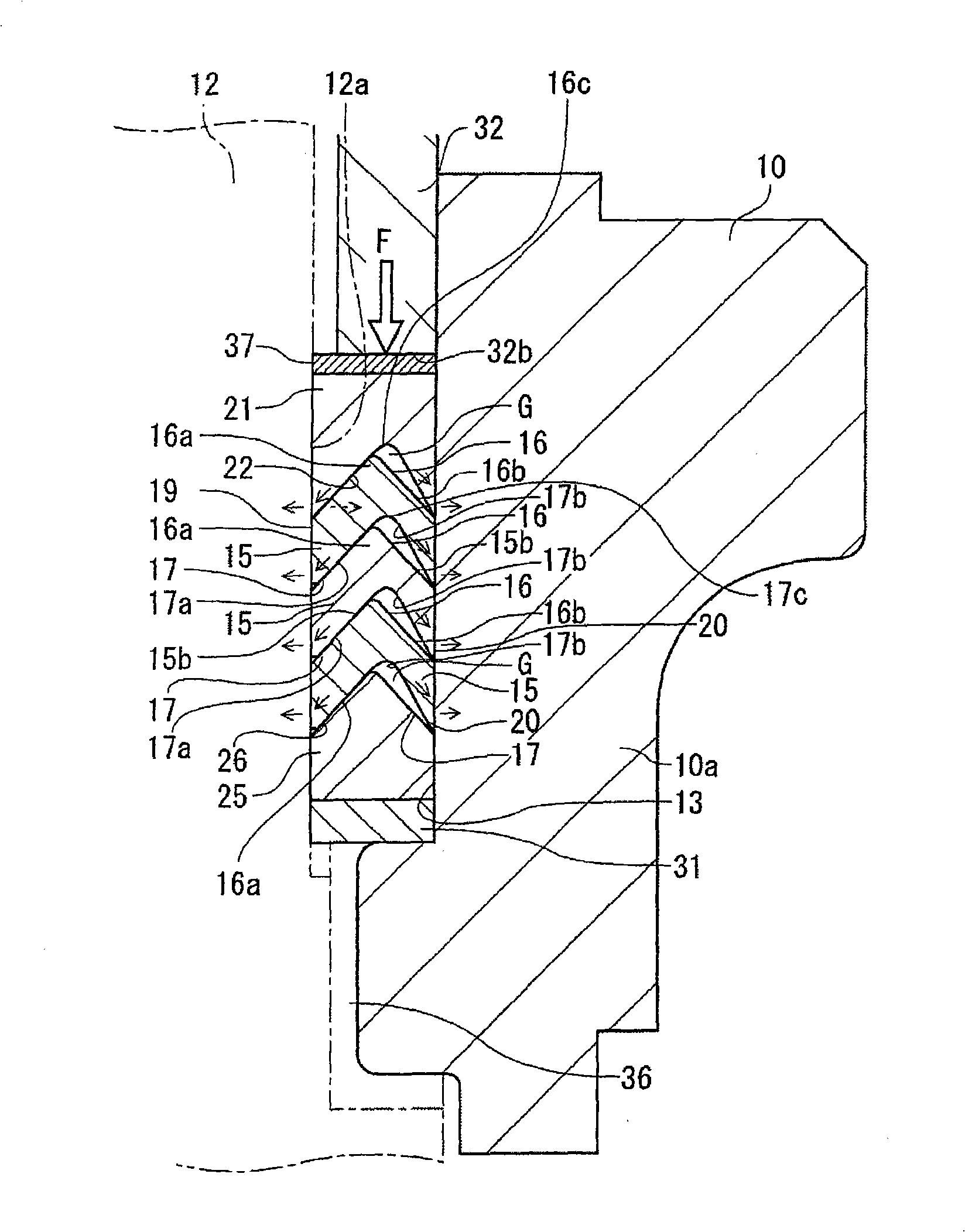
A shaft seal packing exhibiting high sealing ability in initial assembly and also exhibiting, even after the packing is retightened, excellent sealing ability by an increased seal surface pressure obtained through an effect of pressing and by self-sealing ability obtained through an effect of fluid pressure. A valve element installed in a valve body is provided so as to be rotatable about or liftable along a valve shaft. The shaft seal packing is installed in a shaft seal chamber of a valve in which the valve shaft is set. The shaft seal packing is used for a shaft seal structure for the valve, and in the shaft seal packing, annular packing bodies having a generally V-shape cross- section are stacked on each other, the stack surfaces on the inner diameter side are made to be in intimate contact with each other, and a predetermined gap is formed between adjacent stack surfaces on the outer diameter side. In the shaft seal structure, force applied to the packing bodies by tightening force and fluid pressure is converted into radial force by the taper angle of the stack surface on the inner diameter side. This causes the inner peripheral surfaces of the packing bodies on the inner diameter side and the outer peripheral surface of the valve shaft on the sliding side are sealed between each other by surface contact, and also the gaps allow lip parts on the outer diameter side to be pushed and expanded, causing the lip parts and the shaft seal chamber on the fixed side to be sealed between each other by line contact.
Description
technical field [0001] The present invention relates to a shaft seal gasket with improved shaft seal performance, and a valve for organically improving the sealing performance between the dynamic part and the static part and the slidability of the dynamic part of the shaft seal part of valves such as ball valves and gate valves, for example. Shaft seal construction. Background technique [0002] Conventionally, for example, a ball valve has a valve body such as a ball valve body for controlling fluid, and a valve stem for actuating the valve body. In order to open and close the valve by rotating the valve stem, a sealing mechanism is required for the rotating portion of the valve stem. The sealing mechanism of the valve stem rotating portion needs to have a function of reducing frictional force when the valve stem is rotated and maintaining sealing performance with the valve stem and the valve body. In addition, in lift-driven valves such as gate valves, it is also necessar...
Claims
Application Information
Patent Timeline
Application Date:The date an application was filed.
Publication Date:The date a patent or application was officially published.
First Publication Date:The earliest publication date of a patent with the same application number.
Issue Date:Publication date of the patent grant document.
PCT Entry Date:The Entry date of PCT National Phase.
Estimated Expiry Date:The statutory expiry date of a patent right according to the Patent Law, and it is the longest term of protection that the patent right can achieve without the termination of the patent right due to other reasons(Term extension factor has been taken into account ).
Invalid Date:Actual expiry date is based on effective date or publication date of legal transaction data of invalid patent.

